Epic Fitness A17r Bike User Manual - Page 11
Attach the Lower Pivot Cover 12 to the Console
 |
View all Epic Fitness A17r Bike manuals
Add to My Manuals
Save this manual to your list of manuals |
Page 11 highlights
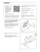
12. Locate the longest wire on the Console (13). Insert that wire downward into the top of the 12 Upright (4) and pull it out of the indicated hole. Connect the other two wires on the Console (13) to the Main Wire Harness (58) and to the Pulse Wire (64). 13 4 Hole 64 58 13. Identify the Lower Pivot Cover (12). 13 Tip: Avoid pinching the wires. It may be necessary to turn the Console Knob (not shown) and adjust the angle of the Console Bracket (35). Attach the Lower Pivot Cover (12) to the Console Bracket (35) with two M4 x 12mm Screws (75). Make sure that the indicated wire is not covered by the Lower Pivot Cover (see the drawing in step 14). 9 77 Avoid 35 pinching the wires 13 75 Next, press the Upper Pivot Cover (9) onto the Lower Pivot Cover (12). Attach the Upper Pivot Cover to the Console (13) with an M4 x 15mm Screw (77). 12 Wire 14. Identify the Right Upright Cover (14), which has the Receiver (59) attached. Hold the Right Upright Cover (14) near the right side of the Upright (4). Connect the wire on the Receiver (59) to the indicated wire. Tip: Avoid pinching the wires. Next, press the Right Upright Cover (14) and the Left Upright Cover (15) together around the Upright (4). 14 14 59 4 Avoid pinching the wires Wire 15 11
-
 1
1 -
2
-
3
-
4
-
5
-
 6
6 -
 7
7 -
 8
8 -
 9
9 -
 10
10 -
 11
11 -
 12
12 -
 13
13 -
 14
14 -
 15
15 -
 16
16 -
17
-
18
-
19
-
20
-
21
-
22
-
23
-
24
-
25
-
26
-
27
-
28
-
29
-
30
-
31
-
32
-
33
-
34
-
35
-
36
 |
 |
