Dell Latitude 5490 Owners Manual
Dell Latitude 5490 Manual
 |
View all Dell Latitude 5490 manuals
Add to My Manuals
Save this manual to your list of manuals |
Dell Latitude 5490 manual content summary:
- Dell Latitude 5490 | Owners Manual - Page 1
Latitude 5490 Owner's Manual Regulatory Model: P72G Regulatory Type: P72G002 - Dell Latitude 5490 | Owners Manual - Page 2
of data and tells you how to avoid the problem. WARNING: A WARNING indicates a potential for property damage, personal injury, or death. © 2018 Dell Inc. or its subsidiaries. All rights reserved. Dell, EMC, and other trademarks are trademarks of Dell Inc. or its subsidiaries. Other trademarks may be - Dell Latitude 5490 | Owners Manual - Page 3
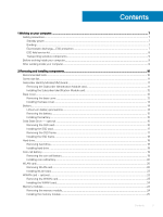
SSD frame...17 Installing the SSD frame...18 Hard drive...18 Removing hard drive...18 Installing hard drive ...19 Coin-cell battery...19 Removing the coin cell battery...19 Installing coin cell battery...20 WLAN card...20 Removing WLAN card...20 Installing WLAN card...23 WWAN card - optional...23 - Dell Latitude 5490 | Owners Manual - Page 4
25 Removing keyboard lattice...25 Installing keyboard lattice...26 Removing the keyboard...26 Installing the keyboard...29 Heat sink ...29 Removing the heat sink ...29 Installing the heat sink ...30 System fan...30 Removing the system fan...30 Installing the system fan...31 Power connector port...32 - Dell Latitude 5490 | Owners Manual - Page 5
...65 Battery specifications...65 AC Adapter specifications...66 System dimensions...67 Operating Conditions...67 4 Technology and components...69 Power adapter...69 Kaby Lake - 7th Generation Intel Core processors 69 Kaby lake Specifications...70 Kaby Lake Refresh - 8th Generation Intel - Dell Latitude 5490 | Owners Manual - Page 6
Software...89 Operating system configurations...89 Downloading drivers...89 Chipset driver...89 Serial IO driver...90 Graphics controller driver...90 USB drivers...90 Network drivers...91 Realtek Audio...91 Serial ATA drivers...91 Security drivers...92 7 Troubleshooting...93 Enhanced Pre-Boot System - Dell Latitude 5490 | Owners Manual - Page 7
instructions service kit when working inside any notebook to avoid electrostatic discharge (ESD) damage. • After removing any system component, carefully place the removed such as intermittent problems or a shortened Dell products, the sensitivity to static damage is now higher than in previous Dell - Dell Latitude 5490 | Owners Manual - Page 8
received a static shock and immediately generates a "No POST/No Video" The more difficult type of damage to recognize and troubleshoot is the intermittent (also called latent or " system being worked on. Once deployed properly, service parts can be removed from the ESD bag and placed directly on - Dell Latitude 5490 | Owners Manual - Page 9
service technicians use the traditional wired ESD grounding wrist strap and protective anti-static mat at all times when servicing Dell Remove any battery designed for this particular Dell computer. Do not use batteries designed for other Dell computers. 1 Connect any external devices, such as a port - Dell Latitude 5490 | Owners Manual - Page 10
Battery • Solid State Drive - optional • Hard drive • Coin-cell battery • WLAN card • WWAN card - optional • Memory modules • Keyboard lattice and Keyboard • Heat sink • System fan • Power connector port screw driver is for screws 0-1 and the #1 screw driver is for screws 2-4 10 Removing and - Dell Latitude 5490 | Owners Manual - Page 11
Latitude 5490 screw size list Component Base cover M2x3 (Thin head) Battery Heatsink 4 WLAN 1 SSD card 1 Keyboard Display assembly Display panel 4 Power connector port .0x2.5 5 M2.5x3 6 Removing the Subscriber Identification Module card CAUTION: Removing the SIM card when the computer - Dell Latitude 5490 | Owners Manual - Page 12
tray into the slot until it clicks into place. Installing the Subscriber Identification Module card 1 Insert a paperclip or a SIM card removal tool into the pinhole [1]. 2 Pull the SIM card tray to remove it [2]. 3 Place the SIM card on the SIM card tray. 4 Push the SIM card tray into the slot until - Dell Latitude 5490 | Owners Manual - Page 13
c Lift the base cover from the system. Removing and installing components 13 - Dell Latitude 5490 | Owners Manual - Page 14
-ion battery can be dangerous. In such an instance, the entire system should be replaced. Contact https://www.dell.com/support for assistance and further instructions. • Always purchase genuine batteries from https://www.dell.com or authorized Dell partners and re-sellers. 14 Removing and installing - Dell Latitude 5490 | Owners Manual - Page 15
in Before working inside your computer. 2 Remove the base cover. 3 To remove the battery: a Disconnect the battery cable from the connector on the system board [1] and unroute the cable from the routing channel. b Loosen the M2x6 captive screw that secures the battery to the system [2]. c Lift the - Dell Latitude 5490 | Owners Manual - Page 16
card NOTE: The following steps are applicable for SATA M.2 2280 and PCIe M.2 2280 1 Follow the procedure in Before working inside your computer. 2 Remove the : a base cover b battery 3 To remove the Solid State Drive (SSD) card: a Peel the adhesive mylar shield that secures the SSD card [1]. NOTE - Dell Latitude 5490 | Owners Manual - Page 17
b base cover 5 Follow the procedure in After working inside your computer. Removing the SSD frame 1 Follow the procedure in Before working inside your computer. 2 Remove the: a base cover b battery c SSD card 3 To remove the SSD frame: a Remove the M2x3 screw that secures the SSD frame to the system - Dell Latitude 5490 | Owners Manual - Page 18
c base cover 4 Follow the procedure in After working inside your computer. Hard drive Removing hard drive 1 Follow the procedure in Before working inside your computer. 2 Remove the : a base cover b battery 3 To remove the hard drive: a Disconnect the hard drive cable from the connector on the - Dell Latitude 5490 | Owners Manual - Page 19
After working inside your system. Coin-cell battery Removing the coin cell battery 1 Follow the procedure in Before working inside your computer. 2 Remove the : a base cover b battery 3 To remove the coin cell battery: a Disconnect the coin cell battery cable from the connector on the system board - Dell Latitude 5490 | Owners Manual - Page 20
cover 4 Follow the procedure in After working inside your computer. WLAN card Removing WLAN card 1 Follow the procedure in Before working inside your computer. 2 Remove the : a base cover b battery 3 To remove the WLAN card: a Remove the M2x3 screw that secures the WLAN card bracket to the system - Dell Latitude 5490 | Owners Manual - Page 21
or chassis frame which helps secure the wireless card in place. When removing the wireless card from the system, make sure the adhesive pad stays on the system board/ chassis frame during the prying process. If the adhesive pad is removed from the system along with the wireless card, adhere it back - Dell Latitude 5490 | Owners Manual - Page 22
22 Removing and installing components - Dell Latitude 5490 | Owners Manual - Page 23
card - optional This is optional as the system might not ship with WWAN card. Removing the WWAN card 1 Follow the procedure in Before working inside your computer. 2 Remove the : a base cover b battery 3 To remove the WWAN card: a Disconnect the WWAN antenna cables from the connectors on the WWAN - Dell Latitude 5490 | Owners Manual - Page 24
base cover 5 Follow the procedure in After working inside your computer. Memory modules Removing the memory module 1 Follow the procedure in Before working inside your computer. 2 Remove the : a base cover b battery 3 To remove the memory module: a Pry the clips securing the memory module until the - Dell Latitude 5490 | Owners Manual - Page 25
slot. Then, press the module until the clips secure the memory module. 2 Install the : a battery b base cover 3 Follow the procedure in After working inside your computer. Keyboard lattice and Keyboard Removing keyboard lattice 1 Follow the procedure in Before working inside your computer. 2 Pry the - Dell Latitude 5490 | Owners Manual - Page 26
procedure in After working inside your computer. Removing the keyboard 1 Follow the procedure in Before working inside your computer. 2 Remove the: a base cover b battery c keyboard lattice 3 To remove the keyboard: a Lift the latch and disconnect the keyboard cable from the connector on the system - Dell Latitude 5490 | Owners Manual - Page 27
c Turn over the system and open the laptop in front view mode. d Remove the five (M2x2.5) screws that secure the keyboard to the system [1]. e Flip the keyboard from the bottom and lift it from the system along with the keyboard cable and the keyboard back light cable [2]. WARNING: Gently pull the - Dell Latitude 5490 | Owners Manual - Page 28
28 Removing and installing components - Dell Latitude 5490 | Owners Manual - Page 29
run through the opening in the frame before connecting them to system board. 5 Install the: a keyboard lattice b battery c base cover 6 Follow the procedure in After working inside your computer. Heat sink Removing the heat sink NOTE: This procedure is only for the UMA model. 1 Follow the procedure - Dell Latitude 5490 | Owners Manual - Page 30
: • Replace the heat sink screws in sequential order as indicated on the heat-sink. 3 Install the : a battery b base cover 4 Follow the procedure in After working inside your computer. System fan Removing the system fan NOTE: This procedure is only for the UMA model 1 Follow the procedure in Before - Dell Latitude 5490 | Owners Manual - Page 31
card g WWAN card (optional) h chassis frame 3 To remove the system fan: a Disconnect the system fan cable from the (optional) c WLAN card d SSD frame e SSD card f hard drive g battery h base cover 4 Follow the procedure in After working inside your computer. Removing and installing components 31 - Dell Latitude 5490 | Owners Manual - Page 32
Power connector port Removing the power connector port 1 Follow the procedure in Before working inside your computer. 2 Remove the : a base cover b battery 3 To remove the power connector port: a Remove the screw that secures the display cable on the system board [1]. b Disconnect the power - Dell Latitude 5490 | Owners Manual - Page 33
Chassis frame Removing the chassis frame 1 Follow the procedure in Before working inside your computer. 2 Remove the: a base cover b battery c hard channels [1]. b Lift the latch and disconnect the keyboard backlight cable and the keyboard cable from their connectors [2,3,4,5] on the system. NOTE - Dell Latitude 5490 | Owners Manual - Page 34
NOTE: There may be more than one cable to connect based on keyboard types. 4 Route the WLAN cables through the routing channels. 5 Install the: a WWAN card (optional) b WLAN card c SSD frame d SSD card e hard drive f battery g base cover 6 Follow the procedure in After working inside your system. 34 - Dell Latitude 5490 | Owners Manual - Page 35
smart card reader board 1 Follow the procedure in Before working inside your computer. 2 Remove the: a base cover b battery c hard drive d SSD card e SSD frame f WLAN card g WWAN card (optional) h chassis frame 3 To release the smart card reader board: a Lift the latch and disconnect - Dell Latitude 5490 | Owners Manual - Page 36
reader board cable and connect the cable to the connector. 5 Install the: a chassis frame b WWAN card (optional) c WLAN card d SSD frame e SSD card f hard drive g battery h base cover 6 Follow the procedure in After working inside your computer. 36 - Dell Latitude 5490 | Owners Manual - Page 37
the procedure in Before working inside your computer. 2 Remove the: a base cover b battery c memory module d hard drive e SSD card f SSD frame g WLAN card h WWAN card (optional) i keyboard lattice j keyboard k chassis frame l system board 3 To remove the speakers: a Release the speaker cable through - Dell Latitude 5490 | Owners Manual - Page 38
1 Follow the procedure in Before working inside your computer. 2 Remove the: a SIM card b base cover c battery d memory module e hard drive f SSD card g SSD frame h WLAN card i WWAN card (optional) j keyboard lattice k keyboard l heat sink m chassis frame n system fan 3 Disconnect the following - Dell Latitude 5490 | Owners Manual - Page 39
the system [2]. c Disconnect the display cables from the connectors on the system board [3,4]. d Disconnect the power connector port cable from the connector on the system board [5]. e Remove the two M2x5 screws that secure the Type-C USB bracket in place [6]. NOTE: The metal bracket secures the - Dell Latitude 5490 | Owners Manual - Page 40
5 To remove the system board: NOTE: Ensure SIM card tray is removed a Remove the four (M2x3) screws that secure the system board in place [1]. b Lift the system board away from the system [2]. 40 Removing and installing components - Dell Latitude 5490 | Owners Manual - Page 41
metal bracket on the DisplayPort over USB Type-C. 5 Connect the power connector port cable to the connector on the system board. 6 Connect the display cables fan b chassis frame c heat sink d keyboard e keyboard lattice f WWAN card (optional) g WLAN card Removing and installing components 41 - Dell Latitude 5490 | Owners Manual - Page 42
procedure in After working inside your computer. Display hinge cover Removing display hinge cover 1 Follow the procedure in Before working inside your computer. 2 Remove the: a base cover b battery 3 To remove the display hinge cover: a Remove the M2x3 screw that secures the display hinge cover to - Dell Latitude 5490 | Owners Manual - Page 43
base cover 5 Follow the procedure in After working inside your computer. Display assembly Removing display assembly 1 Follow the procedure in Before working inside your computer. 2 Remove the: a base cover b battery c WLAN card d WWAN card (optional) e display hinge cover 3 To disconnect the display - Dell Latitude 5490 | Owners Manual - Page 44
4 To release the display assembly: a Remove the two M2x5 screws that secure the display assembly to the computer [1]. b Release the WLAN cable and display cable through the routing channels [2] [3]. 44 Removing and installing components - Dell Latitude 5490 | Owners Manual - Page 45
5 Turn over the computer. 6 To remove the display assembly: a Remove the two M2x5 screws that secure the display assembly to the computer . b Open the display . Removing and installing components 45 - Dell Latitude 5490 | Owners Manual - Page 46
c Lift the display assembly from the computer. 46 Removing and installing components - Dell Latitude 5490 | Owners Manual - Page 47
bracket to the system. 11 Route the WLAN and WWAN cables through the routing channels. 12 Install the: a hinge cover b WWAN card (optional) c WLAN card d battery e base cover 13 Follow the procedure in After working inside your computer. Removing and installing components 47 - Dell Latitude 5490 | Owners Manual - Page 48
in Before working inside your computer. 2 Remove the: a base cover b battery c WLAN card d WWAN card (optional) e Display hinge cover f display assembly 3 To remove the display bezel: a Pry the display bezel at the base of the display [1]. NOTE: When removing or reinstalling the display bezel from - Dell Latitude 5490 | Owners Manual - Page 49
cover 4 Follow the procedure in After working inside your computer. Display panel Removing display panel 1 Follow the procedure in Before working inside your computer. 2 Remove the: a base cover b battery c WLAN card d WWAN card (optional) e display hinge cover f display assembly g display bezel - Dell Latitude 5490 | Owners Manual - Page 50
4 To remove the display panel: a Peel the conductive tape [1]. b Remove the adhesive strip that secures the display cable [2]. c Lift the latch and disconnect the display cable from the connector on the display panel [3] [4]. 50 Removing and installing components - Dell Latitude 5490 | Owners Manual - Page 51
screws to secure the display panel to the display back cover. 5 Install the: a display bezel b display assembly c display hinge cover d WLAN card e WWAN card (optional) f battery g base cover 6 Follow the procedure in After working inside your computer. Removing and installing components 51 - Dell Latitude 5490 | Owners Manual - Page 52
cable 1 Follow the procedure in Before working inside your computer. 2 Remove the: a base cover b battery c WLAN card d WWAN card (optional) e display hinge cover f display assembly g display bezel h display panel 3 Disconnect the camera cable from the connector on the camera module [1]. 4 - Dell Latitude 5490 | Owners Manual - Page 53
h base cover 4 Follow the procedure in After working inside your computer. Camera Removing camera 1 Follow the procedure in Before working inside your computer. 2 Remove the: a base cover b battery c WLAN card d WWAN card (optional) e display hinge cover f display assembly g display bezel h display - Dell Latitude 5490 | Owners Manual - Page 54
cover 4 Follow the procedure in After working inside your computer. Display hinges Removing display hinge 1 Follow the procedure in Before working inside your computer. 2 Remove the: a base cover b battery c WLAN card d WWAN card (optional) e display assembly f display bezel g display hinge cover - Dell Latitude 5490 | Owners Manual - Page 55
a display hinge cover b display bezel c display assembly d WLAN card e WWAN card (optional) f battery g base cover 5 Follow the procedure in After working inside your computer. Display back cover assembly Removing the display back cover assembly 1 Follow the procedure in Before working inside your - Dell Latitude 5490 | Owners Manual - Page 56
c display hinge d display panel e display bezel f display assembly g display hinge cover h WLAN card i WWAN card (optional) j battery k base cover 3 Follow the procedure in After working inside your computer. Palm rest Removing palm rest 1 Follow the procedure in Before working inside your computer - Dell Latitude 5490 | Owners Manual - Page 57
base cover c battery d memory module e hard drive f SSD card g SSD frame h WLAN card i WWAN card (optional) j keyboard lattice k keyboard l heat sink m chassis frame n system fan o system board p display hinge cover q display assembly 3 The palm rest is the remaining component after removing all the - Dell Latitude 5490 | Owners Manual - Page 58
f heat sink assembly g keyboard h keyboard lattice i WWAN card (optional) j WLAN card k SSD frame l SSD card m hard drive n memory module o battery p base cover q SIM card 3 Follow the procedure in After working inside your computer. 58 Removing and installing components - Dell Latitude 5490 | Owners Manual - Page 59
Ports and Connectors • Contacted smart card specifications • Display specification • Keyboard specifications • Touch pad specifications • Battery Processors Support List UMA Graphics Intel® Core™ i3-7130U (Dual Core, 3M Cache, 2.7GHz,15W) Intel® HD Graphics 620 Intel® Core™ i5-7300U - Dell Latitude 5490 | Owners Manual - Page 60
Maximum Memory Configuration Number of slots Maximum memory supported per slot Memory options Type Speed 4 GB 16 GB • 32 GB - 2 x 16 GB DDR4 • 2400 MHz for 8th Gen Processor • 2133 MHz for 7th Gen Processor Storage specifications NOTE: Depending on the x2 NVMe SSD Dell Fast Response Free - Dell Latitude 5490 | Owners Manual - Page 61
Feature Specification • Noise reducing array microphones • Volume control buttons, supports hot-key keyboard button External interface Stereo headset/mic combo Speakers Two Volume controls Hot keys Video specification Integrated Feature Type UMA controller Specification Integrated on - Dell Latitude 5490 | Owners Manual - Page 62
Ports and Connectors Table 6. Ports and Connectors USB Video Network Modem Expansion Smart Card Reader Touch Fingerprint Reader Contactless card reader Audio Docking Noise reducing array microphones Volume control buttons, supports hot-key keyboard button DisplayPort over USB Type C™ Noble Wedge - Dell Latitude 5490 | Owners Manual - Page 63
Types HD (1366 x 768) Anti-glare (16:9) WLED FHD WVA (1920 x 1080) Embedded Touch Display with Truelife (OTP Lite) Specifications Luminance/Brightness (typical) • 220 nits Native Resolution • 1920x1080 Refresh Rate • 60 Hz Horizontal Viewing Angle • +85/- 85 degrees Vertical Viewing Angle • +85/- - Dell Latitude 5490 | Owners Manual - Page 64
perform secondary functions. To type the alternate character, press Shift and the desired key. To perform secondary functions, press Fn and the desired key. Table 8. Keyboard hot key definitions Fn Key Combination Fn+ESC Fn+ F1 Fn + F2 Fn + F3 Fn + F4 Fn + F5 Fn + F6 Fn + F8 Fn + F9 Fn - Dell Latitude 5490 | Owners Manual - Page 65
ExpressCharge Capable Battery • 3 cell, 51 Whr ExpressCharge Capable Battery • 4 cell, 68 Whr ExpressCharge Capable Battery • 4 cell, Long Cycle Life Battery Windows 10 Supported Supported Supported Supported Supported Supported Supported Supported Supported Supported Supported Supported Technical - Dell Latitude 5490 | Owners Manual - Page 66
4 cell, 68 Whr • Length: 233mm (9.17 inch) • Width: 95.9mm (3.78 inch) • Height: 7.05mm (0.28 inch) • Weight: 340.00 g 4 cell, Long Cycle Life Battery • Length: 233mm (9.17 inch) • Width: 95.9mm (3.78 inch) • Height: 7.05mm (0.28 inch) • Weight: 340.00 g Voltage 42 Whr 51 Whr 68 Whr 4 cell Long - Dell Latitude 5490 | Owners Manual - Page 67
Feature Input voltage Input current (maximum) Specification 100 V AC to 240 V AC • 65 W adapter - 1.7 A • 65 W BFR/PVC Halogen Free adapter - 1.7 A • 90 W adapter - 1.6 A Adapter size Input frequency Output current 7.4 mm 50 Hz to 60 Hz • 65 W adapter - 3.34 A (continuous) • 65 W BFR/PVC Halogen - Dell Latitude 5490 | Owners Manual - Page 68
Relative humidity Altitude (maximum) Shock Vibration • Storage: -40 °C to 65 °C (-40 °F to 149 °F • Operating : 10 % to 90 % (non-condensing) • Storage: 0% to 95% (non-condensing) • Operating : 3048 m (10,000 ft) • Storage: 10668 m (35,000 ft) • Operating: 160 G with pulse duration of 2 ms ( - Dell Latitude 5490 | Owners Manual - Page 69
7th Generation Intel Core processors • Kaby Lake Refresh - 8th Generation Intel Core processors • DDR4 • HDMI 1.4 • HDMI 1.4 • USB features • USB Type-C Power adapter This laptop is Smart Cache • Optional Intel vPro technology (on i5/i7) with Active Management Technology 11.6 • Intel Rapid Storage - Dell Latitude 5490 | Owners Manual - Page 70
GHz Intel Core i5-7200U (3M Cache, up to 3.1 GHz), Dual Core 2.5 GHz Intel Core i5-7300U (3M Cache, up to 3.5 GHz),vPro, Dual Core 2.6 GHz Intel Core i7-7600U (4M 8th Generation Intel Core processors The 8th Gen Intel Core processor (Kaby Lake Refresh) family is the successor of 7th generation - Dell Latitude 5490 | Owners Manual - Page 71
i7-8650U 4.2 GHz 8 MB Intel Core i7-8550U 4.0 GHz 8 MB Intel Core i5-8350U 3.6 GHz 6 MB Intel Core i5 graphics 620 DDR4 (double data rate fourth generation) memory is a higher-speed successor to volts of electrical power to operate. DDR4 also supports a new, deep power-down mode that allows - Dell Latitude 5490 | Owners Manual - Page 72
. Troubleshoot for possible memory failure by trying known good memory modules in the memory connectors on the bottom of the system or under the keyboard, as advantage is cable reduction and content protection provisions. HDMI supports standard, enhanced, or high-definition video, plus multichannel - Dell Latitude 5490 | Owners Manual - Page 73
for additional color models used in digital photography and computer graphics • 4K Support - Enables video resolutions far beyond 1080p, supporting next-generation displays that will rival the Digital Cinema systems used in many commercial movie theaters • HDMI Micro Connector - A new, smaller - Dell Latitude 5490 | Owners Manual - Page 74
simplified the connection between host computers and peripheral devices like mice, keyboards, external drivers, and printers. Let's take a quick look on the USB • New power management features • Full-duplex data transfers and support for new transfer types • Backward USB 2.0 compatibility • New - Dell Latitude 5490 | Owners Manual - Page 75
Drives • Portable USB 3.0/USB 3.1 Gen 1 Hard Drives • USB 3.0/USB 3.1 Gen 1 Drive Docks & Adapters • USB 3.0/USB 3.1 Gen 1 Flash Drives & Readers • USB 3.0/USB 3.1 support for USB 3.1 Gen 1 controllers. This is in contrast to previous versions of Windows, which continue to require separate drivers - Dell Latitude 5490 | Owners Manual - Page 76
standard that every device should be able to use. USB Type-C ports can support a variety of different protocols using "alternate modes," which allows you to laptop charging cables, with everything charging via a standard USB connection. You could charge your laptop from one of those portable battery - Dell Latitude 5490 | Owners Manual - Page 77
• Manageability • Virtualization support screen options • Wireless drive). During the Power-on Self Test (POST), when the Dell logo appears, you can: • Access System Setup by pressing the diagnostic option. The boot menu options are: • Removable Drive (if available) • STXXXX Drive NOTE: XXX denotes - Dell Latitude 5490 | Owners Manual - Page 78
system configuration information after you add, change, or remove any hardware in your computer. • Set or your computer and try again. NOTE: After the Dell logo appears, you can also press F12 and then Service Tag, Asset Tag, Ownership Tag, Ownership Date, Manufacture Date, and the Express Service - Dell Latitude 5490 | Owners Manual - Page 79
, Video BIOS Version, Video Memory, Panel Type, Native Resolution, Audio Controller, Wi-Fi Device, WiGig Device, Cellular Device, Bluetooth Device. Battery Information Displays the battery status and the type of AC adapter connected to the computer. Boot Sequence Allows you to change the order in - Dell Latitude 5490 | Owners Manual - Page 80
Support: This option is enabled by default. • Enable External USB Port: This option is enabled by default. NOTE: USB keyboard and mouse always work in the BIOS setup irrespective of these settings. Dell Type-C Dock depending up on the power source (On Battery and On AC). NOTE: The video setting - Dell Latitude 5490 | Owners Manual - Page 81
Security screen options Option Admin Password Description Allows you to set, change, or delete the administrator (admin) password. NOTE: You must set the admin password before you set the system or hard drive password. Deleting the admin password automatically deletes the system password and the - Dell Latitude 5490 | Owners Manual - Page 82
NOTE: To upgrade or downgrade TPM1.2/2.0, download the TPM wrapper tool (software). Computrace CPU XD Support Allows you to activate or disable the the Execute Disable mode of the processor. Enable CPU XD Support (default) OROM Keyboard Access Allows you to set an option to enter the Option - Dell Latitude 5490 | Owners Manual - Page 83
sets SGX Enclave Reserve Memory Size. The option are: • 32 MB • 64 MB • 128 MB Performance screen options Option Description Multi Core Support This field specifies whether the process has one or all cores enabled. The performance of some applications improves with the additional cores. • All - Dell Latitude 5490 | Owners Manual - Page 84
when the AC power adapter is connected. If the AC power adapter is removed during Standby, the system setup removes power from all the USB ports to conserve battery power. • Enable USB Wake Support • Wake on Dell USB-C Dock: This option is enabled by default. Wireless Radio Control Allows you to - Dell Latitude 5490 | Owners Manual - Page 85
Allows you to select the charging mode for the battery. The options are: • Adaptive (default) • Standard - Fully charges your battery at a standard rate. • ExpressCharge - The battery charges over a shorter period of time using Dell's fast charging technology. This option is enabled by default - Dell Latitude 5490 | Owners Manual - Page 86
Option Keypad (Embedded) Description Allows you to choose one of two methods to enable the keypad that is embedded in the internal keyboard. • Fn Key Only: This option is enabled by default. • By Numlock NOTE: When setup is running, this option has no effect. Setup works in Fn - Dell Latitude 5490 | Owners Manual - Page 87
Virtualization support screen options Option Virtualization Description Allows you to All the options are enabled by default. Maintenance screen options Option Service Tag Asset Tag BIOS Downgrade Description Displays the Service Tag of your computer. Allows you to create a system asset - Dell Latitude 5490 | Owners Manual - Page 88
Option Data Wipe BIOS Recovery Description This field allows users to erase the data securely from all internal storage devices. The following is list of devices affected: • Internal SATA HDD/SSD • Internal M.2 SATA SDD • Internal M.2 PCIe SSD • Internal eMMC This field allows you to recover from - Dell Latitude 5490 | Owners Manual - Page 89
notebook. 2 Go to Dell.com/support. 3 Click Product Support, enter the Service Tag of your notebook, and then click Submit. NOTE: If you do not have the Service Tag, use the auto detect feature or manually browse for your notebook model. 4 Click Drivers and Downloads. 5 Select the operating system - Dell Latitude 5490 | Owners Manual - Page 90
card Serial IO driver Verify if the drivers for Touchpad, IR camera, and keyboard and are installed. Figure 4. Serial IO driver Graphics controller driver Verify if the graphics controller driver is already installed in the computer. Table 16. Graphics controller driver Before Installation After - Dell Latitude 5490 | Owners Manual - Page 91
and Bluetooth drivers from the Dell support site. Table 17. Network drivers Before installation After installation Realtek Audio Verify if audio drivers are already installed in the computer. Table 18. Realtek audio Before Installation After Installation Serial ATA drivers Install the latest - Dell Latitude 5490 | Owners Manual - Page 92
Security drivers This section lists the security devices in the Device Manager. Security device drivers Verify if the security device drivers are installed in the computer. Fingerprint sensor drivers Verify if the Fingerprint sensor drivers are installed in the computer. 92 Software - Dell Latitude 5490 | Owners Manual - Page 93
that inform you if tests are completed successfully • View error messages that inform you of problems encountered during testing CAUTION: Use the system diagnostics to test only your computer. Using this issues, error codes are displayed. Note the error code and contact Dell. Troubleshooting 93 - Dell Latitude 5490 | Owners Manual - Page 94
the computer. 2 As the computer boots, press the F12 key when the Dell logo is displayed. 3 In the boot menu screen, use Up/Down arrow date and time. The following items are unaffected by the RTC reset: • Service Tag • Asset Tag • Ownership Tag • Admin Password • System Password • 94 Troubleshooting - Dell Latitude 5490 | Owners Manual - Page 95
options. Availability varies by country and product, and some services may not be available in your area. To contact Dell for sales, technical support, or customer service issues: 1 Go to Dell.com/support. 2 Select your support category. 3 Verify your country or region in the Choose a Country
-
 1
1 -
 2
2 -
 3
3 -
 4
4 -
 5
5 -
 6
6 -
 7
7 -
8
-
9
-
10
-
11
-
12
-
13
-
14
-
15
-
16
-
17
-
18
-
19
-
20
-
21
-
22
-
23
-
24
-
25
-
26
-
27
-
28
-
29
-
30
-
31
-
32
-
33
-
34
-
35
-
36
-
37
-
38
-
39
-
40
-
41
-
42
-
43
-
44
-
45
-
46
-
47
-
48
-
49
-
50
-
51
-
52
-
53
-
54
-
55
-
56
-
57
-
58
-
59
-
60
-
61
-
62
-
63
-
64
-
65
-
66
-
67
-
68
-
69
-
70
-
71
-
72
-
73
-
74
-
75
-
76
-
77
-
78
-
79
-
80
-
81
-
82
-
83
-
84
-
85
-
86
-
87
-
88
-
89
-
90
-
91
-
92
-
93
-
94
-
95
 |
 |

Latitude 5490
Owner’s Manual
Regulatory Model: P72G
Regulatory Type: P72G002