Lenovo ThinkServer TD200x Hardware Maintenance Manual for TD200x - Page 180
the other end of the power cord to a properly grounded electrical outlet.
 |
View all Lenovo ThinkServer TD200x manuals
Add to My Manuals
Save this manual to your list of manuals |
Page 180 highlights
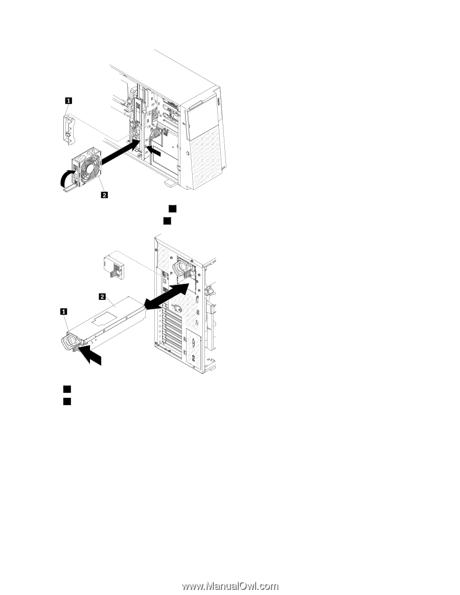
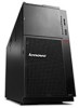
000000 000000 000000 000000 000000 000000 000000 000000 000000 000000 000000 000000 3. Remove the three fan air baffles 1 from the fan bays of the fan cage assembly. 4. Install the three hot-swap fans 2 in the empty bays of the fan cage assembly. 000 000 000 000 000 000 00000 00000 00000 00000 00000 00000 00000 00000 00000 00 00 00 00 00 00 00 1 Release latch 2 Hot-swap power supply 5. Remove the power supply filler from the second power supply bay. 6. Slide the new power supply partially into the empty power supply bay. Pinch the orange release latch and push the power supply the rest of the way into the bay until it is seated. 7. Install the left-side cover. 8. Connect one end of the new power cord into the connector on the back of power supply, and connect the other end of the power cord to a properly grounded electrical outlet. 9. Make sure that the ac power LED on the top of each power supply is lit, indicating that the power supply is operating correctly. If the server is turned on, make sure that the dc power LED on the top of the power supply is lit also. If you have other optional devices to install or remove, do so now. Otherwise, go to Completing the installation. 172 ThinkServer TD200x Hardware Maintenance Manual
-
 1
1 -
2
-
3
-
4
-
5
-
6
-
7
-
8
-
9
-
10
-
11
-
12
-
13
-
14
-
15
-
16
-
17
-
18
-
19
-
20
-
21
-
22
-
23
-
24
-
25
-
26
-
27
-
28
-
29
-
30
-
31
-
32
-
33
-
34
-
35
-
36
-
37
-
38
-
39
-
40
-
41
-
42
-
43
-
44
-
45
-
46
-
47
-
48
-
49
-
50
-
51
-
52
-
53
-
54
-
55
-
56
-
57
-
58
-
59
-
60
-
61
-
62
-
63
-
64
-
65
-
66
-
67
-
68
-
69
-
70
-
71
-
72
-
73
-
74
-
75
-
76
-
77
-
78
-
79
-
80
-
81
-
82
-
83
-
84
-
85
-
86
-
87
-
88
-
89
-
90
-
91
-
92
-
93
-
94
-
95
-
96
-
97
-
98
-
99
-
100
-
101
-
102
-
103
-
104
-
105
-
106
-
107
-
108
-
109
-
110
-
111
-
112
-
113
-
114
-
115
-
116
-
117
-
118
-
119
-
120
-
121
-
122
-
123
-
124
-
125
-
126
-
127
-
128
-
129
-
130
-
131
-
132
-
133
-
134
-
135
-
136
-
137
-
138
-
139
-
140
-
141
-
142
-
143
-
144
-
145
-
146
-
147
-
148
-
149
-
150
-
151
-
152
-
153
-
154
-
155
-
156
-
157
-
158
-
159
-
160
-
161
-
162
-
163
-
164
-
165
-
166
-
167
-
168
-
169
-
170
-
171
-
172
-
173
-
174
-
 175
175 -
 176
176 -
 177
177 -
 178
178 -
 179
179 -
 180
180 -
 181
181 -
 182
182 -
 183
183 -
 184
184 -
 185
185 -
186
-
187
-
188
-
189
-
190
-
191
-
192
-
193
-
194
-
195
-
196
-
197
-
198
-
199
-
200
-
201
-
202
-
203
-
204
-
205
-
206
-
207
-
208
-
209
-
210
-
211
-
212
-
213
-
214
-
215
-
216
-
217
-
218
-
219
-
220
-
221
-
222
-
223
-
224
-
225
-
226
-
227
-
228
-
229
-
230
-
231
-
232
-
233
-
234
-
235
-
236
-
237
-
238
-
239
-
240
-
241
-
242
-
243
-
244
-
245
-
246
-
247
-
248
-
249
-
250
-
251
-
252
-
253
-
254
-
255
-
256
-
257
-
258
-
259
-
260
-
261
-
262
-
263
-
264
-
265
-
266
-
267
-
268
-
269
-
270
-
271
-
272
-
273
-
274
-
275
-
276
-
277
-
278
-
279
-
280
-
281
-
282
-
283
-
284
-
285
-
286
-
287
-
288
-
289
-
290
 |
 |