Dell Vostro 5471 Ownerss Manual
Dell Vostro 5471 Manual
 |
View all Dell Vostro 5471 manuals
Add to My Manuals
Save this manual to your list of manuals |
Dell Vostro 5471 manual content summary:
- Dell Vostro 5471 | Ownerss Manual - Page 1
Dell Vostro 5471 Owners's Manual Regulatory Model: P88G Regulatory Type: P88G001 - Dell Vostro 5471 | Ownerss Manual - Page 2
and tells you how to avoid the problem. WARNING: A WARNING indicates a potential for property damage, personal injury, or death. © 2018 - 2019 Dell Inc. or its subsidiaries. All rights reserved. Dell, EMC, and other trademarks are trademarks of Dell Inc. or its subsidiaries. Other trademarks may - Dell Vostro 5471 | Ownerss Manual - Page 3
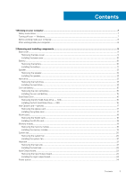
on your computer...7 Safety instructions...7 Turning off your - Windows...7 Before working inside your computer...8 After working inside your computer...8 2 Removing and installing components 9 Base cover...9 Removing the base cover...9 Installing the base cover...10 Battery...10 Removing the - Dell Vostro 5471 | Ownerss Manual - Page 4
hinge...37 Installing display hinge...37 DC-in...38 Removing the DC-in...38 Installing the DC-in...38 Keyboard lattice and Keyboard...39 Removing the keyboard...39 Installing the keyboard...40 Palm rest...41 Removing and installing palmrest...41 eDP cable...42 Removing the eDP cable...42 Installing - Dell Vostro 5471 | Ownerss Manual - Page 5
Keyboard...52 Touchpad specification...52 Camera...52 Storage specification...52 Battery support 66 Updating the Dell BIOS in Linux drivers...72 Chipset drivers...72 Graphics controller driver...73 USB drivers...74 Network drivers...74 Audio drivers...74 Storage controller drivers...74 Other drivers - Dell Vostro 5471 | Ownerss Manual - Page 6
7 Troubleshooting...76 Dell Enhanced Pre-Boot System Assessment - ePSA Diagnostic 3.0 76 Running the ePSA Diagnostics...76 Diagnostic LED...76 Battery status lights...77 8 Contacting Dell...78 6 Contents - Dell Vostro 5471 | Ownerss Manual - Page 7
computer, replace all troubleshooting and simple repairs as authorized in your product documentation, or as directed by the online or telephone service and support team. Damage due to servicing that is not authorized by Dell is not covered by your warranty. Read and follow the safety instructions - Dell Vostro 5471 | Ownerss Manual - Page 8
To avoid damage to the computer, use only the battery designed for this particular Dell computer. Do not use batteries designed for other Dell computers. 1. Connect any external devices, such as a port replicator or media base, and replace any cards, such as an ExpressCard. 2. Connect any telephone - Dell Vostro 5471 | Ownerss Manual - Page 9
2 Removing and installing components Base cover Removing the base cover 1. Follow the procedure in Before working inside your computer. 2. To remove the base cover: a) Remove the eight M2.5 x 6 screws [1]. b) Loosen the two M2.5 x 6 screws [2]. c) Pry the base cover from the edge [1]. NOTE: You may - Dell Vostro 5471 | Ownerss Manual - Page 10
it clicks into place. 3. Tighten the two M2.5 x 6 screws. 4. Replace the eight M2.5 x 6 screws to secure the base cover to the computer. 5. Follow computer. 2. Remove the base cover. 3. To remove the battery: a) Disconnect the battery cable [1] from the connector on the system board. b) Lift - Dell Vostro 5471 | Ownerss Manual - Page 11
d) Remove the four M2.0 x 3 screws [1]. e) Lift the battery away from the system [2]. Installing the battery 1. Insert the battery into the slot on the computer. 2. Connect the battery cable to the connector on the system board. Removing and installing components 11 - Dell Vostro 5471 | Ownerss Manual - Page 12
3. Connect the hard disk drive cable to the connector on the system board and close the latch. 4. Replace the four M2.0 x 3 screws to secure the battery to the system. 5. Install the base cover. 6. Follow the procedure in After working inside your computer. Speaker Removing the speaker 1. Follow the - Dell Vostro 5471 | Ownerss Manual - Page 13
system. 2. Route the speaker cable through the routing tabs on the system. 3. Connect the speaker cable to the system board. 4. Install the: a) battery b) base cover 5. Follow the procedure in After working inside your computer. Hard drive Removing the hard drive 1. Follow the procedure in Before - Dell Vostro 5471 | Ownerss Manual - Page 14
to the system [1]. b) Lift the hard drive away from the system [2]. Installing the hard drive 1. Insert the hard drive into the slot on the system. 2. Replace the four M2.0 x 3 screws to secure the hard drive assembly to the system. 14 Removing and installing components - Dell Vostro 5471 | Ownerss Manual - Page 15
release from the adhesive and lift it away from the system board [2]. Installing the coin cell battery 1. Place the coin cell battery into the slot on the system board. 2. Connect the coin cell battery cable to the connector on the system board. 3. Install the base cover. 4. Follow the procedure in - Dell Vostro 5471 | Ownerss Manual - Page 16
1. Align the notch on the solid-state drive with the tab on the solid-state drive slot. 2. Slide the solid-state drive into the slot. 3. Replace the M2.0 x 3 screw to secure the SSD to the system. 4. Install the base cover. 5. Follow the procedure in After working inside your computer. 16 Removing - Dell Vostro 5471 | Ownerss Manual - Page 17
optane card 1. Affix the thermal pad into the slot on the system board. 2. Insert the Optane card into the card slot on the system board. 3. Replace the M2.0 x 3 screw to secure the Optane card to the system. 4. Install the base cover. 5. Follow the procedure in After working inside your computer - Dell Vostro 5471 | Ownerss Manual - Page 18
Insert the WLAN card into the slot on the system. 2. Connect the WLAN cables to the connectors on the WLAN Card. 3. Place the bracket and replace the M2.0 x 4 screw to secure it to the system. 4. Install the base cover. 5. Follow the procedure in After working inside your computer. 18 Removing and - Dell Vostro 5471 | Ownerss Manual - Page 19
Memory module Removing the memory module 1. Follow the procedure in Before working inside your computer. 2. Remove the base cover. 3. To remove the memory module: a) Peel the adhesive tape to a 90 degree angle above the memory module [1]. b) Using your finger tips gently pry the retention clips away - Dell Vostro 5471 | Ownerss Manual - Page 20
System fan Removing the system fan 1. Follow the procedure in Before working inside your computer. 2. Remove the base cover. 3. To remove the system fan: a) Disconnect the system fan cable from the connector on the system board. b) Remove the two M2.0 x 4 screws that secure the system fan to the - Dell Vostro 5471 | Ownerss Manual - Page 21
Installing the system fan 1. Place the system fan into the slot on the system. 2. Replace the two M2.0 x 4 screws to secure it to the system. 3. Connect the system fan cable to the connector on the system board. 4. Install the base - Dell Vostro 5471 | Ownerss Manual - Page 22
Installing the heat sink 1. Place the heat sink to its slot in the system. 2. Tighten the seven M2.0 x 3 screws to secure the heat sink to the system board. 3. Install the: a) system fan b) base cover 4. Follow the procedure in After working inside your computer. Input Output board Removing the - Dell Vostro 5471 | Ownerss Manual - Page 23
d) Remove the two M2.0 x 4 screws that secure the I/O board to the system [1]. e) Lift the I/O board away from the system. Removing and installing components 23 - Dell Vostro 5471 | Ownerss Manual - Page 24
Installing the Input output board 1. Place the Input output(I/O) board to its slot in the system. 2. Replace the two M2.0 x 4 screws to secure the I/O board to the system board. 3. Connect the I/O cable and the fingerprint cable and close the latch to secure - Dell Vostro 5471 | Ownerss Manual - Page 25
c) Lift the latch and disconnect the power button cable from the connector in the fingerprint board. d) Remove the two M2.0 x 3 screws securing the power button to the system [1]. e) Lift the button away from the system [2]. Removing and installing components 25 - Dell Vostro 5471 | Ownerss Manual - Page 26
button 1. Place the power button to its slot in the system. 2. Replace the screws to secure the power button to the system. 3. Connect the working inside your computer. 2. Remove the: a) base cover b) battery c) system fan d) heat sink e) solid-state drive(SSD) 26 Removing and installing components - Dell Vostro 5471 | Ownerss Manual - Page 27
3. To remove the system board: a) Disconnect the following cables: • Input output(I/O) board cable [1,2] • Input output(I/O) board cable [3] • Keyboard backlight cable [4] • Keyboard and Touchpad cable [5] b) Disconnect the eDP cable [1], power adapter port cable [2] and speaker cable [5] from the - Dell Vostro 5471 | Ownerss Manual - Page 28
e) Remove the three M2.0 x 2 screws that secure the system board to the system [1]. f) Lift and remove the system board from the system [2]. 28 Removing and installing components - Dell Vostro 5471 | Ownerss Manual - Page 29
screw holes on the system board and replace the two screws to secure the bracket keyboard backlight cable, keyboard cable and touchpad cable to the system board. 6. Install the: a) solid state drive(SSD) b) heat sink c) system fan d) battery secure the touchpad support bracket to the system and - Dell Vostro 5471 | Ownerss Manual - Page 30
the three screws to secure the touchpad support bracket to the system. 2. Connect the touchpad cable to the connector in the system. 3. Replace the four screws to secure the touchpad to the system. 4. Install the: a) hard drive b) battery c) base cover 5. Follow the procedure in After working - Dell Vostro 5471 | Ownerss Manual - Page 31
c) Lift and slide the display assembly. d) The component you are left with is the display assembly. Removing and installing components 31 - Dell Vostro 5471 | Ownerss Manual - Page 32
Installing display assembly 1. Align and place the display assembly on the system. 2. Place the hinge bracket on the system and replace the screws to secure the display assembly to the system. 3. Connect the eDP cable to the connector in the system board. 4. Install the: a) WLAN card b) - Dell Vostro 5471 | Ownerss Manual - Page 33
b) Remove the display bezel from display assembly. Installing display bezel 1. Place the display bezel on the display assembly. 2. Starting from the top corner, press on the display bezel and work around the entire bezel until it clicks on to the display assembly. 3. Install the: a) display - Dell Vostro 5471 | Ownerss Manual - Page 34
b) WLAN card c) base cover 4. Follow the procedure in After working inside your computer. Camera Removing the camera 1. Follow the procedure in Before working inside your computer. 2. Remove the: a) base cover b) WLAN card c) display assembly d) display bezel 3. To remove the camera: a) Slide the - Dell Vostro 5471 | Ownerss Manual - Page 35
a) display bezel b) display assembly c) WLAN card d) base cover 4. Follow the procedure in After working inside your computer. Display panel Removing display panel 1. Follow the procedure in Before working inside your computer. 2. Remove the: a) base cover b) WLAN card c) display assembly d) display - Dell Vostro 5471 | Ownerss Manual - Page 36
panel 1. Connect the eDP cable to the connector. 2. Affix the adhesive tape to secure the eDP cable. 3. Replace the display panel to align with the screw holders on the display assembly. 4. Replace the four screws to secure the display panel to the display assembly. 5. Install the: a) display bezel - Dell Vostro 5471 | Ownerss Manual - Page 37
b) Lift the display hinge away from the display assembly [2]. Installing display hinge 1. Place the display hinge cover on the display assembly. 2. Replace the screws to secure the display hinge cover to the display assembly. 3. Install the: a) display panel b) display bezel c) display assembly - Dell Vostro 5471 | Ownerss Manual - Page 38
to its slot in the system. 2. Connect the power-adapter port cable to the connector in the system board. 3. Place the right display hinge and replace the 3 screws to secure the hinge to the system. 4. Install the: a) display assembly 38 Removing and installing components - Dell Vostro 5471 | Ownerss Manual - Page 39
c) base cover 5. Follow the procedure in After working inside your computer. Keyboard lattice and Keyboard Removing the keyboard 1. Follow the procedure in Before working inside your computer. 2. Remove the: a) base cover b) battery c) system fan d) heat sink e) solid state drive(SSD) f) WLAN card - Dell Vostro 5471 | Ownerss Manual - Page 40
on to the slot on the palm rest. 2. Replace the screws that secure the keyboard on the palm rest. 3. Place the keyboard bracket above the keyboard in to the system slot. 4. Replace the screws to secure the keyboard to the system. 5. Install the: a) display assembly 40 Removing and installing - Dell Vostro 5471 | Ownerss Manual - Page 41
g) solid state drive(SSD) h) heat sink i) system fan j) battery k) base cover 6. Follow the procedure in After working inside your computer Input output(I/O) board j) power button k) hard drive l) system board m) keyboard n) display assembly NOTE: After the removal of all the components the component - Dell Vostro 5471 | Ownerss Manual - Page 42
components on the new palm rest: a) display assembly b) keyboard c) system board d) hard drive e) powered button f) Input Output(I/O) board g) WLAN card h) solid state drive(SSD) i) heat sink j) system fan k) touchpad l) speaker m) battery n) base cover 4. Follow the procedure in After working - Dell Vostro 5471 | Ownerss Manual - Page 43
Installing the eDP cable 1. Place the eDP cable on the display panel. 2. Route the eDP cable through the routing channel. 3. Install the: a) display hinge b) display panel c) camera d) display bezel e) display assembly f) WLAN card g) base cover 4. Follow the procedure in After working inside your - Dell Vostro 5471 | Ownerss Manual - Page 44
Installing the display back cover 1. The display back cover assembly is the remaining component, after removing all the components. 2. Install the: a) eDP cable b) display hinge c) display panel d) camera e) display bezel f) display assembly g) WLAN card h) base cover 3. Follow the procedure in - Dell Vostro 5471 | Ownerss Manual - Page 45
memory into the system. DDR4 needs 20 percent less or just 1.2 volts, compared to DDR3 which requires 1.5 volts of electrical power to operate. DDR4 also supports a new, deep power-down mode that allows the host device to go into standby without needing to refresh its memory. Deep power-down mode is - Dell Vostro 5471 | Ownerss Manual - Page 46
Troubleshoot for possible memory failure by trying known good memory modules in the memory connectors on the bottom of the system or under the keyboard, as in some portable systems. NOTE: The DDR4 memory is imbedded in board and not a replaceable duplex data transfers and support for new transfer - Dell Vostro 5471 | Ownerss Manual - Page 47
to previous versions of Windows, which continue to require separate drivers for USB 3.0/USB 3.1 Gen 1 controllers. Microsoft announced that Windows 7 would have USB 3.1 Gen 1 support, perhaps not on its immediate release, but in a subsequent Service Pack or update. It is not out of the question - Dell Vostro 5471 | Ownerss Manual - Page 48
standard that every device should be able to use. USB Type-C ports can support a variety of different protocols using "alternate modes," which allows you to have You could charge your laptop from one of those portable battery packs you charge your smartphones and other portable devices from - Dell Vostro 5471 | Ownerss Manual - Page 49
video and multichannel audio into a single cable, eliminating the cost, complexity, and confusion of multiple cables currently used in A/V systems • HDMI supports communication between the video source (such as a DVD player) and the DTV, enabling new functionality Technology and components 49 - Dell Vostro 5471 | Ownerss Manual - Page 50
(1 x 4 GB) Maximum memory 32 GB Video specification Feature Video controller: Memory Specification • Intel Integrated UHD Graphics 620 (8th Gen Core i5, i7 processors) • AMD Radeon 530 Graphics with 2GB/4GB GDDR5 vRAM • Shared system memory • 2 GB/4 GB GDDR5 dedicated memory Audio specification - Dell Vostro 5471 | Ownerss Manual - Page 51
Communication specification Feature Ethernet adapter Wireless Specification Network interface card capable of 10/100/1000 mb/s communication WLAN options: • DW1820 2x2 ac 802.11ac+BT4.1 • 2x2 AC(Intel 7265) and 1x1 AC(Intel 3165 & DW1810) totally 3 cards Ports and connectors specification - Dell Vostro 5471 | Ownerss Manual - Page 52
Keyboard Feature Number of keys Layout Specification • United States: 80 keys 128 GB M.2 SSD • 256 GB M.2 SSD • 512 GB M.2 SSD • HDD Free Fall Sensor (FFS) Support Battery specification Feature Wattage Type Length Height Specification 42 Whr (3 Cell) Lithium-ion/polymer Li-ion/polymer 175.36 mm - Dell Vostro 5471 | Ownerss Manual - Page 53
Non-Operating -20° C to 60° C (4° F to 140° F) Typical Amp-hour 3.684Ahr capacity Typical Watt-hour 42 Whr capacity Coin-cell battery 3 V CR2032 lithium ion cell AC adapter Feature Wattage Input voltage Input current (maximum) Input frequency Output current (continuous) Rated output voltage Height - Dell Vostro 5471 | Ownerss Manual - Page 54
Feature Width (inches/mm) Depth (inches/mm) Specification 343 mm (13.50 inch) 240.8 mm (9.48 inch) Environmental specification Feature Temperature range: Operating Storage Relative humidity (maximum): Storage Maximum vibration: Operating Storage Maximum shock: Operating Storage Maximum Altitude: - Dell Vostro 5471 | Ownerss Manual - Page 55
Topics: • Boot menu • Navigation keys • System setup options • Updating the BIOS in Windows • System and setup password Boot menu Press when the Dell™ logo appears to initiate a one-time boot menu with a list of the valid boot devices for the system. Diagnostics and BIOS Setup options are - Dell Vostro 5471 | Ownerss Manual - Page 56
its installed devices, the items listed in this section may or may not appear. General options Table 2. General Option System Information Battery Information Boot Sequence Advanced Boot Options UEFI Boot Path Security Date/Time Description This section lists the primary hardware features of your - Dell Vostro 5471 | Ownerss Manual - Page 57
you to enable or disable the internal/integrated USB configuration. The options are: • Enable USB Boot Support • Enable External USB Ports All the options are set by default. NOTE: USB keyboard and mouse always work in the BIOS setup irrespective of these settings. This field configures the USB - Dell Vostro 5471 | Ownerss Manual - Page 58
-Default The Keyboard Backlight with AC option does not affect the main keyboard illumination feature. Keyboard Illumination will continue to support the various illumination to set the display brightness depending upon the power source. On Battery(50% is default) and On AC (100 % default). Security - Dell Vostro 5471 | Ownerss Manual - Page 59
Option System Password Description Allows you to set, change, or delete the System password. The entries to set password are: • Enter the old password: • Enter the new password: • Confirm new password: Click OK once you set the password. NOTE: For the first time login, "Enter the old password:" - Dell Vostro 5471 | Ownerss Manual - Page 60
password is set. • Enable Admin Setup Lockout This option is not set by default. Master Password Lockout Allows you to disable master password support. • Enable Master Password Lockout This option is not set by default. NOTE: Hard Disk password should be cleared before the settings can be - Dell Vostro 5471 | Ownerss Manual - Page 61
Memory Size Click one of the following options: • 32 MB • 64 MB • 128 MB-Default Performance Table 8. Performance Option Multi Core Support Intel SpeedStep C-States Control Description This field specifies whether the process has one or all cores enabled. The performance of some applications - Dell Vostro 5471 | Ownerss Manual - Page 62
is not set by default. USB Wake Support Allows you to enable USB devices to wake the system from standby. • Enable USB Wake Support This option is not set by default. at times of peak demand. Advanced Battery Charge This option enables you to maximize the battery health. By enabling this option, - Dell Vostro 5471 | Ownerss Manual - Page 63
for the battery. The options are: • Adaptive-Default • Standard - Fully charges your battery at a standard rate. • ExpressCharge- The battery charges over a shorter period of time using Dell's fast charging button press has been acknowledged by turning on the keyboard backlight. System setup 63 - Dell Vostro 5471 | Ownerss Manual - Page 64
Warnings • Continue on Warnings and Errors Virtualization support Table 11. Virtualization Support Option Description Virtualization This option specifies whether Maintenance Table 13. Maintenance Option Description Service Tag Displays the service tag of your computer. 64 System setup - Dell Vostro 5471 | Ownerss Manual - Page 65
option controls the automatic boot flow for Support Assist System Resolution Console and Dell OS Recovery tool. Click one of the BIOS (System Setup), when you replace the system board or if an update is available. For laptops, ensure that your computer battery is fully charged and connected to - Dell Vostro 5471 | Ownerss Manual - Page 66
Dell.com/support. • Enter the Service Tag or Express Service Code and click Submit. • Click Detect Product and follow the instructions on screen. 3. If you are unable to detect or find the Service Support page of your computer appears. 6. Click Get drivers and click Drivers and Downloads. The Drivers - Dell Vostro 5471 | Ownerss Manual - Page 67
does not have to be bootable) • BIOS executable file that you downloaded from the Dell Support website and copied to the root of the USB key • AC power adapter connected to the system • Functional system battery to flash the BIOS Perform the following steps to execute the BIOS update flash process - Dell Vostro 5471 | Ownerss Manual - Page 68
3. The Bios flash menu will open then click the Flash from file. 4. Select external USB device 68 System setup - Dell Vostro 5471 | Ownerss Manual - Page 69
5. Once the file is selected, Double click the flash target file, then press submit . 6. Click the Update BIOS then system will reboot to flash the BIOS. System setup 69 - Dell Vostro 5471 | Ownerss Manual - Page 70
7. Once complete, the system will reboot and the BIOS update process is completed. System and setup password Table 16. System and setup password Password type System password Description Password that you must enter to log on to your system. Setup password Password that you must enter to access - Dell Vostro 5471 | Ownerss Manual - Page 71
Deleting or changing an existing system setup password Ensure that the Password Status is Unlocked (in the System Setup) before attempting to delete or change the existing System and/or Setup password. You cannot delete or change an existing System or Setup password, if the Password Status is Locked - Dell Vostro 5471 | Ownerss Manual - Page 72
by Vostro 5471 Table 17. Operating systems Windows 10 • Microsoft Windows 10 Home 64 bit • Microsoft Windows10 Professional 64 bit • Microsoft Windows 10 National Academic 64-bit (Bid Desk) Others • Ubuntu 16.04 LTS 64-bit Downloading drivers 1. Turn on the computer. 2. Go to Dell.com/support - Dell Vostro 5471 | Ownerss Manual - Page 73
Graphics controller driver Verify if the graphics controller driver is already installed in the computer. Software 73 - Dell Vostro 5471 | Ownerss Manual - Page 74
are already installed in the computer. Network drivers The driver is labeled as Intel I219-LM Ethernet Driver. Audio drivers Verify if the audio drivers are already installed in the computer. Storage controller drivers Verify if the storage controller drivers are already installed in the computer - Dell Vostro 5471 | Ownerss Manual - Page 75
if the human interface device drivers are already installed in the computer. Firmware Verify if the Firmware drivers are already installed in the computer. Intel Dynamic Platform and Thermal Framework Verify if the Intel Dynamic Platform and Thermal Framework drivers are already installed in the - Dell Vostro 5471 | Ownerss Manual - Page 76
, on Notebooks, battery codes for Low Battery or Battery Failure situations will not be displayed when Diagnostic Error Codes are being displayed: Table 18. LED pattern Blinking pattern Problem Description Suggested Resolution Amber White 2 1 processor processor failure 76 Troubleshooting - Dell Vostro 5471 | Ownerss Manual - Page 77
with AC adapter present. Re-plug battery connector, replace battery if the issue reoccurs. Fatal battery failure with AC adapter present. Fetal battery, replace the battery. Battery in full charge mode with AC adapter present. Battery in charge mode with AC adapter present. Troubleshooting 77 - Dell Vostro 5471 | Ownerss Manual - Page 78
options. Availability varies by country and product, and some services may not be available in your area. To contact Dell for sales, technical support, or customer service issues: 1. Go to Dell.com/support. 2. Select your support category. 3. Verify your country or region in the Choose a Country
-
 1
1 -
 2
2 -
 3
3 -
 4
4 -
 5
5 -
 6
6 -
 7
7 -
8
-
9
-
10
-
11
-
12
-
13
-
14
-
15
-
16
-
17
-
18
-
19
-
20
-
21
-
22
-
23
-
24
-
25
-
26
-
27
-
28
-
29
-
30
-
31
-
32
-
33
-
34
-
35
-
36
-
37
-
38
-
39
-
40
-
41
-
42
-
43
-
44
-
45
-
46
-
47
-
48
-
49
-
50
-
51
-
52
-
53
-
54
-
55
-
56
-
57
-
58
-
59
-
60
-
61
-
62
-
63
-
64
-
65
-
66
-
67
-
68
-
69
-
70
-
71
-
72
-
73
-
74
-
75
-
76
-
77
-
78
 |
 |

Dell Vostro 5471
Owners's Manual
Regulatory Model: P88G
Regulatory Type: P88G001