Adaptec FS4500 User Guide
Adaptec FS4500 - Hard Drive Array Manual
 |
UPC - 760884144275
View all Adaptec FS4500 manuals
Add to My Manuals
Save this manual to your list of manuals |
Adaptec FS4500 manual content summary:
- Adaptec FS4500 | User Guide - Page 1
2U STORAGE ENCLOSURE INSTALLATION & USER'S GUIDE FS4100, FS4500, SC4100, AND FC4100 - Adaptec FS4500 | User Guide - Page 2
information only and is subject to change without notice. While reasonable efforts have been made in the preparation of this document to assure its accuracy, Adaptec, Inc. assumes no liability resulting from errors or omissions in this document, or from the use of the information contained herein - Adaptec FS4500 | User Guide - Page 3
Friday, 3:00 A.M. to 5:00 P.M., Pacific Time. ■ For RAID and Fibre Channel products call +1 321-207-2000, Monday to Friday, 3:00 A.M. to 5:00 P.M., Pacific Time. To expedite your service, have your computer in front of you. ■ To order Adaptec products, including accessories and cables, call +1 408 - Adaptec FS4500 | User Guide - Page 4
, call +49 89 43 66 55 33, Monday to Friday, 9:00 to 17:00, CET. For support via e-mail, submit your question to Adaptec's Technical Support Specialists at ask-fr.adaptec.com. ■ English: To speak with a Technical Support Specialist, call +49 89 43 66 55 44, Monday to Friday, 9:00 to 17:00, GMT - Adaptec FS4500 | User Guide - Page 5
product during the warranty period to an authorized Adaptec service facility or to Adaptec and providing proof of purchase price and date. The purchaser shall bear all shipping TO YOU. 8. This warranty gives you specific legal rights, and you may also have other rights which vary from state to state. - Adaptec FS4500 | User Guide - Page 6
may not use the Software in a computer service business, including in time sharing applications. The other copies may exist. This license is not a sale of the Software or any copy. 5. Confidentiality. You all copies or modifications in any form. Adaptec will have the right to terminate our license - Adaptec FS4500 | User Guide - Page 7
may last, so the above limitations may not apply to you. This warranty gives you specific legal rights and you may also have other rights which vary from state to state. 9. The entire liability of Adaptec and its licensors, and your exclusive remedy for a breach of this warranty, shall be: a. The - Adaptec FS4500 | User Guide - Page 8
used in accordance with the instruction manual, may cause harmful interference - EN61000-4-4 (1995) Electrical fast transients/burst: ±1 kV AC, ±0.5 kV I/O - EN61000-4-5 (1995) Surges ±1 kV riel brouilleur du Canada. Japanese Compliance (Voluntary Control Council Initiative) This is a class A product - Adaptec FS4500 | User Guide - Page 9
Need in this Guide 1-2 Kit Contents Connecting the I/O Cables 2-9 Connecting SATA Cables 2-10 Connecting FC Cables 2-11 Modules. 2-13 Next Steps 2-13 3 Monitoring About the ES Module 3-2 Silencing the Audible Alarm 3-2 Understanding the LEDs 3-3 Front Panel LEDs 3-3 Drive Carrier LEDs 3-4 APC Module - Adaptec FS4500 | User Guide - Page 10
Module LEDs 5-5 SATA I/O Module Configuration 5-7 FS4100 I/O Module Configuration 5-7 FS4500 I/O Module Configuration 5-7 Drive Carrier LEDs 5-7 6 Fibre Channel Storage Enclosures (FC4100) About the Fibre Channel Storage Enclosure 6-2 Disk Drive Spin-up Sequence 6-2 I/O Modules 6-2 Supported Fibre - Adaptec FS4500 | User Guide - Page 11
Fibre Channel Cables 6-3 Fibre Channel ID Assignment 6-5 Disk Drive Loop Identifier Map 6-5 LIO JBOD Module About the Adaptec SC4100 Storage Enclosure 7-2 Disk Drive Spin-up Sequence 7-2 I/O Modules 7-2 Drive -Bus 7-6 8 Technical Specifications General Specifications 8-2 System 8-2 Redundant - Adaptec FS4500 | User Guide - Page 12
Technical Specifications 8-7 Currently Supported Disk Drives 8-7 Serial ATA Interface 8-8 SATA I/O Modules 8-8 SATA Cables 8-8 SATA Configurations 8-8 FC Storage Enclosure Technical Specifications 8-9 Disk Drives 8-9 Daisy Chaining Adaptec FC Enclosures 8-9 A Configuring the RAID Controller (FS4500 - Adaptec FS4500 | User Guide - Page 13
Contents View and Edit Drives (Select Drive) Option A-7 View and Edit Channels (Select Channel) Option A-8 View and Edit Configuration Parameters Option A-9 View and Edit Peripheral Devices Option A-11 System Functions Option A-11 View System Information Option A-12 View and Edit Event Logs Option - Adaptec FS4500 | User Guide - Page 14
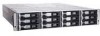
1 Introduction In this Chapter.... About This Guide 1-2 Finding the Information You Need in this Guide 1-2 Kit Contents 1-3 Overview of the Storage Enclosure 1-3 This chapter introduces the Adaptec 2U Storage Enclosure documented in this Guide and provides an overview of the enclosure's - Adaptec FS4500 | User Guide - Page 15
Introduction About This Guide This Guide explains how to set up and use Adaptec's 2U Storage Enclosures. The models supported by this manual are: ■ Adaptec FS4100 Fibre Channel-to-Serial ATA JBOD enclosure ■ Adaptec FS4500 Fibre Channel-to-Serial ATA RAID enclosure ■ Adaptec SC4100 Ultra320 SCSI - Adaptec FS4500 | User Guide - Page 16
Advanced Power and Cooling (APC) modules ■ Two I/O Option modules (SATA, FC, or SCSI, depending on the interface of your Storage Enclosure model) Your Adaptec Storage Enclosure also features one hot-swappable (but non-redundant) Enclosure Services (ES) module, which includes the Alarm Mute button - Adaptec FS4500 | User Guide - Page 17
Front of Storage Enclosure Introduction Disk Drive Carrier LEDs Disk Drive Carriers Rear of Storage Enclosure ES Module Alarm Mute Button APC Module I/O Module 2 I/O Module1 I/O Option Modules (FC Model shown here) Figure 1-1 Overview of Storage Enclosure APC Module 1-4 - Adaptec FS4500 | User Guide - Page 18
For more detailed information about these components, see the chapter of this Guide dedicated to your specific Storage Enclosure interface: ■ For a SATA interface (Adaptec FS4100 or FS4500), see Chapter 5. ■ For an FC interface (Adaptec FC4100), see Chapter 6. ■ For an Ultra320 SCSI interface - Adaptec FS4500 | User Guide - Page 19
I/O Cables Step 5: Connect Power Cords to the APC Modules. Next Steps 2-2 2-2 2-3 2-9 2-9 2-13 2-13 This chapter explains how to set up the Storage Enclosure and install it in a rackmount or tower assembly (optional.) For model-specific connection and configuration information, see Chapter 5 to - Adaptec FS4500 | User Guide - Page 20
Enclosure Installation Checklist For a smooth and trouble-free installation, thoroughly review this chapter and perform the tasks in Connect the AC power cords to the APC modules. See page 2-13. 5 Connect the I/O cables. See page 2-9. 6 Go to the chapter for your specific Storage Enclosure interface - Adaptec FS4500 | User Guide - Page 21
to a grounded power outlet. Leave enough room behind the rack for servicing and to allow for sufficient airflow. ■ Decide on a suitable location sold separately. To purchase a rail kit, see your Adaptec reseller. Follow the instructions in this section if you are installing your Storage Enclosure - Adaptec FS4500 | User Guide - Page 22
screws (10 large, 4 small) ■ Two types of nuts (10 of each) To install your Storage Enclosure in a rack: 1 Secure the front rails to the front supports of the rack, using the supplied screws, as shown in Figure 2-1. Note: Use either the speednuts or cagenuts provided if your rack does not have - Adaptec FS4500 | User Guide - Page 23
Installing the Storage Enclosure 3 Secure the rear rails you selected to the rear supports of the equipment rack, using the supplied screws, as shown in Figure 2-1 on page 2-4. 4 Secure the front rails to the rear rails, as shown in - Adaptec FS4500 | User Guide - Page 24
Installing the Storage Enclosure You can choose to have someone continue to support the enclosure until it is secured in the rack, although this extra support is not required. Figure 2-3 Storage Enclosure in Rack 8 Secure the front of the enclosure with one screw on each side, as shown in Figure - Adaptec FS4500 | User Guide - Page 25
Installing the Storage Enclosure Installing into a Tower Assembly ! Caution: Do not modify the tower assembly. The feet are designed to keep the tower from tipping over. Do not remove the acoustic foam inside the tower skin assembly. 1 If the Storage Enclosure is already set up and running, shut - Adaptec FS4500 | User Guide - Page 26
Installing the Storage Enclosure 5 Slide the enclosure into the tower skin, as shown in Figure 2-6. Figure 2-6 Sliding Storage Enclosure into Tower Skin 6 Replace the front bezel, using the screws removed in Step 3. 7 Install the tower labels at the top and bottom of the tower. Align the holes in - Adaptec FS4500 | User Guide - Page 27
with Step 5: Connect Power Cords to the APC Modules. Step 4: Connecting the I/O Cables To connect the I/O cables to your Storage Enclosure, follow the instructions provided for your specific Storage Enclosure interface: ■ For a SATA interface (Adaptec FS4100 or FS4500), see page 2-10. ■ For an FC - Adaptec FS4500 | User Guide - Page 28
that support copper or optical cables. Ensure that you have the appropriate SFP installed for your cables. See the Adaptec 2U Storage Enclosure Installation and User's Guide on the CD for more cabling information and for daisychaining instructions. JBOD Configuration (FS4100) FS4100 SATA I/O Module - Adaptec FS4500 | User Guide - Page 29
that support copper or optical cables. Ensure that you have the appropriate SFP installed for your cables. See the Adaptec 2U Storage Enclosure Installation and User's Guide on the CD for more cabling information and for daisy-chaining instructions. Single Loop Configuration FC4100 FC I/O Module - Adaptec FS4500 | User Guide - Page 30
and User's Guide on the CD for supported cable lengths and additional cabling information. ! Caution: Use only Ultra320 certified cables. Ultra160 certified cables are not supported by the Adaptec SC4100 Storage Enclosure. Single Bus Configuration SC4100 SCSI I/O Module HOST BUS ADAPTER - Adaptec FS4500 | User Guide - Page 31
5: Connect Power Cords to the APC Modules. Connect one of the supplied power cords to each of the APC modules and to a grounded power outlet. ! for your specific Storage Enclosure interface: ■ For a SATA interface (Adaptec FS4100 or FS4500), see Chapter 5. ■ For an FC interface (Adaptec FC4100), see - Adaptec FS4500 | User Guide - Page 32
, which reports enclosure status through the use of LEDs and an audible alarm. The chapter describes the monitoring features of the Adaptec Storage Enclosure, including the ES module, the alarm, and the LEDs, and explains how to use these features to monitor the status of your enclosure's components - Adaptec FS4500 | User Guide - Page 33
alarm manually by pressing the Alarm Mute button on the ES module (shown module is reset or until another alarm occurs. Note: You can also silence the alarm using Adaptec Storage Examiner software. See the Installation and User's Guide on your Adaptec Storage Enclosure CD for detailed instructions - Adaptec FS4500 | User Guide - Page 34
more LED information for the Adaptec Storage Enclosure, see the chapter in this Guide that's dedicated to the specific interface for your enclosure. (Chapter Enclosure power off 2 3 2 Shelf fault No shelf fault 3 FS4100/FS4500: 4 Enclosure speed is Enclosure speed is 3 GB/second 1.5 GB/ - Adaptec FS4500 | User Guide - Page 35
of the three LEDs for all Adaptec Storage Enclosure models and interfaces. Table 3-2 Drive Carrier LEDs Interface U320 SCSI (SC4100) FC (FC4100) SATA (One FS4100 I/O Module) SATA (Two FS4100 I/O Modules) SATA (One FS4500 I/O Module) SATA (Two FS4500 I/O Modules) LED 1 (Green) Not used. Not used - Adaptec FS4500 | User Guide - Page 36
Table 3-4 Drive Carrier LED 3 Interface U320 SCSI (SC4100) FC (FC4100) SATA (FS4100 or FS4500) Spin Up On Blinking Off Drive Status Online I/O Activity Off On (briefly) On Off (briefly) On Off (briefly) APC Module LEDs Each APC module has two LEDs, which are visible from the rear of the - Adaptec FS4500 | User Guide - Page 37
Monitoring The LEDs function as described in Table 3-5: Table 3-5 APC Module LEDs LED Green Yellow On APC functioning normally APC failure Blinking N/A Failure predicted Off Enclosure is not powered on APC functioning normally 3-6 - Adaptec FS4500 | User Guide - Page 38
provides detailed instructions for removing and replacing failed or damaged components of your Adaptec Storage Enclosure. ! Caution: Before touching any of the Storage Enclosure components, ground yourself and take antistatic precautions. Adaptec recommends that you use an antistatic wrist strap and - Adaptec FS4500 | User Guide - Page 39
. For drive carrier installation instructions, see page 2-9. About the Drive Carriers The drive carriers are located on the front of the Storage Enclosure. (See Figure 1-1 on page 1-4.) The drive carriers have a mechanical button-activated cam system that helps control installation and removal, and - Adaptec FS4500 | User Guide - Page 40
carrier (or carrier blank) out of the enclosure. 5 Immediately replace the removed drive carrier or install a carrier blank to maintain correct airflow and cooling. For instructions on installing a drive carrier, see Step 3: Installing the Drive Carriers on page 2-9. 4-3 - Adaptec FS4500 | User Guide - Page 41
This section provides basic information about your Storage Enclosure's APC modules, including removal and installation instructions. About the APCs Each APC is a self-contained power supply with an integral cooling fan. Your Adaptec Storage Enclosure includes two APCs, located on the rear of the - Adaptec FS4500 | User Guide - Page 42
Before you remove an APC, ensure that you have a replacement module ready for immediate installation so that proper cooling and airflow are : 1 Power off the failed APC module and remove the power cable. If the enclosure is powered on, the fans in both APC modules switch to high speed. The cooling - Adaptec FS4500 | User Guide - Page 43
. To install an APC into the Storage Enclosure: 1 Ensure that the handles of the new APC module are lowered (open). Note: Do not use the handles to lift or carry the APC modules. 2 Holding the APC module with the handles towards you, slide it into the empty slot. 3 Gently push up on both - Adaptec FS4500 | User Guide - Page 44
, and they are interface-specific. A blank I/O module may also be available for single I/O module configurations. (For detailed information about your I/O modules, see the chapter dedicated to your specific interface: ■ For a SATA interface (Adaptec FS4100 or FS4500), see Chapter 5. ■ For an - Adaptec FS4500 | User Guide - Page 45
fix the I/O module into place. 4 Secure the module by tightening the two screws you loosened in Step 3 on page 4-8. Hand-tighten the screws. Do not overtighten them. 5 Connect the I/O cables, as described in the chapter of this Guide that is dedicated to your specific Storage Enclosure's interface - Adaptec FS4500 | User Guide - Page 46
Removing and Replacing Enclosure Components ■ For a SATA interface (Adaptec FS4100 or FS4500), see Chapter 5. ■ For an FC interface (Adaptec FC4100), see Chapter 6. ■ For an Ultra320 SCSI interface (Adaptec SC4100), see Chapter 7. 4-9 - Adaptec FS4500 | User Guide - Page 47
Replacing Enclosure Components Hot-swapping the ES Module This section provides removal and installation instructions for your Storage Enclosure's ES modules. For detailed information about the ES module and how it works, see About the ES Module on page 3-2. The ES module is located on the rear of - Adaptec FS4500 | User Guide - Page 48
it as part of a complete storage subsystem. The Adaptec SATA Storage Enclosure can be configured as either a JBOD or as a RAID enclosure: ■ The FS4100 has one or two JBOD I/O modules. ■ The FS4500 has one or two RAID I/O modules. This chapter provides the configuration and cabling information for - Adaptec FS4500 | User Guide - Page 49
Receptacles Figure 5-1 SATA I/O Module Table 5-1 shows the I/O modules available for your Adaptec SATA Storage Enclosure: Table 5-1 SATA I/O Modules Model Number Adaptec FS4100 Adaptec FS4500 Host Connection Fibre Channel Fibre Channel Disk Connection SATA SATA Disk Organization JBOD RAID 5-2 - Adaptec FS4500 | User Guide - Page 50
the host HBA connector selection. The Adaptec SATA Storage Enclosure uses a SATA interface to the hard disk drives. This SATA interface supports data rates of 1.5 Gb/sec. The Adaptec FS4500 Storage Enclosure supports RAID levels 0, 1, 0+1, 3, 5, 10, 30, and 50. SATA Cables Hosts communicate with the - Adaptec FS4500 | User Guide - Page 51
, and can be connected to one, two, three, or four hosts. Note: You cannot include Adaptec FS4100 and Adaptec FS4500 I/O modules together in the same Storage Enclosure. Dual SATA configurations provide a redundant controller and make better use of the available FC front-end bandwidth. The redundant - Adaptec FS4500 | User Guide - Page 52
FS4500) Daisy-chaining Adaptec SATA Storage Enclosures You can daisy-chain up to eight FS4100 Storage Enclosures in a system. You can daisy-chain up to seven FS4100 Storage Enclosures behind an FS4500 ES module on the back of the Storage Enclosure. (See Figure 3-1 on page 3-2.) Adaptec recommends - Adaptec FS4500 | User Guide - Page 53
SATA I/O module. Figure 5-1 on page 5-2 shows the LEDs on the I/O module. The LEDs are numbered as shown below. 5678 1234 For more information, see the LED descriptions provided for your specific Storage Enclosure: ■ For the Adaptec FS4100, see Table 5-4 on page 5-7. ■ For the Adaptec FS4500, see - Adaptec FS4500 | User Guide - Page 54
on SATA port No I/O activity 7a Partner Failed Partner controller failure detected Partner controller operating normally 8 Controller Ready Controller active and Controller not ready operating normally a In single controller configurations, this LED is not used. Table 5-5 FS4500 I/O Module - Adaptec FS4500 | User Guide - Page 55
87% or more original charge capacity) SATA I/O Module Configuration This section describes how to configure the two I/O modules. FS4100 I/O Module Configuration The Adaptec FS4100 I/O module supports JBOD and does not require configuring. FS4500 I/O Module Configuration Use the Spheras RAIDWatch - Adaptec FS4500 | User Guide - Page 56
About the Fibre Channel Storage Enclosure 6-2 LIO JBOD Module Configurations 6-6 2 Gb/sec Operation 6-7 Daisy-chaining FC Storage Enclosures 6-7 LIO Module LEDs 6-7 Option Slot Loop AL_PA Assignments 6-7 Storage Enclosure LEDs 6-8 This chapter introduces the Adaptec FC4100 Storage - Adaptec FS4500 | User Guide - Page 57
the Fibre Channel Storage Enclosure Disk Drive Spin-up Sequence The two APC modules in Modules The Adaptec FC Storage Enclosure can accommodate two LIO modules, although it is possible to have only one. LIO modules are a combination of an LRC3 module and a copper or optical module. The LIO modules - Adaptec FS4500 | User Guide - Page 58
high ■ Downloadable firmware ■ Drive device control bits for 1, 2 and other FCAL controlled by Storage Enclosure ■ Speed operations ■ +5 and +12 VDC on the drive connector Fibre Channel Cables This section describes the cables supported by the Adaptec FC Storage Enclosure. Copper Cables FCAL copper - Adaptec FS4500 | User Guide - Page 59
Fibre Channel Storage Enclosures (FC4100) Table 6-1 Supported 1 Gb/sec Copper Cables Cable Length 0.3 m 0.5 m 1.0 m 1.0 m 3.0 m 3.0 m 5.0 m 5.0 m 10 m (1 Gb/sec only) Connectors SFP/SFP SFP/SFP SFP/SFP SFP/HSSDC SFP/HSSDC SFP/SFP SFP/SFP SFP/HSSDC SFP/HSSDC Optical Cables Lengths Supported for 1 - Adaptec FS4500 | User Guide - Page 60
Channel Storage Enclosures (FC4100) Fibre Channel ID Assignment Each FC drive slot has a unique between 0 and 9, using the ID switch on the ES module, shown in Figure 1-1 on page 1-4. When you power-on the enclosure, the ES module and LIO module read the ID switch setting and set the enclosure ID. - Adaptec FS4500 | User Guide - Page 61
Fibre Channel Storage Enclosures (FC4100) LIO JBOD Module Configurations This section describes the FC configurations supported by your Adaptec FC Storage Enclosure. Note: All FC enclosures require the use of an appropriate SFP transducer (copper or optical). Single Loop (Nonredundant) Operation - Adaptec FS4500 | User Guide - Page 62
and entire enclosure will operate at 2 Gb/sec. The LIO module does not support auto-negotiation of the FC loop speed. Daisy-chaining FC Storage Enclosures You can daisy-chain Adaptec FC Storage Enclosures to a total of 120 disk drives. Speed Mismatches between Enclosures When Storage Enclosures - Adaptec FS4500 | User Guide - Page 63
Fibre Channel Storage Enclosures (FC4100) Table 6-4 LIO Module LEDs LED On 1 I/O channel fault in either single or split loop mode 2 Dual Loop configuration 3 LIO functioning normally 4 Loop running at 2 Gb/sec Off Loop - Adaptec FS4500 | User Guide - Page 64
7 Ultra320 SCSI Storage Enclosures In this Chapter.... About the Adaptec SC4100 Storage Enclosure 7-2 Ultra320 SCSI Split-bus Configurations 7-4 Ultra320 SCSI Joined-bus Configurations 7-5 This chapter introduces the Adaptec SC4100 Ultra320 SCSI Storage Enclosure and describes how to cable - Adaptec FS4500 | User Guide - Page 65
for the location of each drive slot. I/O Modules The Adaptec SC4100 Storage Enclosure has two I/O modules available-the Adaptec JBOD I/O module and the Joiner module. SCSI JBOD I/O Module The Adaptec SC4100 Storage Enclosure supports one SCSI JBOD I/ O module, which can be located in either of - Adaptec FS4500 | User Guide - Page 66
module inserted, the bus will be split. (See Replacing an I/O Module on page 4-7 for installation instructions.) Note: If you are not using a Joiner module for detailed information about LED functions. Cables and Termination The Adaptec Ultra320 Storage Enclosure is self-terminated for single- and - Adaptec FS4500 | User Guide - Page 67
Split-bus Configurations Note: The Ultra320 Storage Enclosure does not support daisychaining JBOD shelves. A split-bus configuration has two separate busses with up to six disk drives on each bus. In this configuration, the enclosure has an I/O module in one I/O slot, and an I/O blank in the other - Adaptec FS4500 | User Guide - Page 68
the hosts. High-quality Ultra320 SCSI cables are available for sale on the Adaptec Web site at www.adaptec.com. To connect a split-bus enclosure to one or the enclosure has an I/O module in one I/O slot, and an Joiner module in the other. You must use a Joiner module to use the Ultra320 Storage - Adaptec FS4500 | User Guide - Page 69
use high-quality Ultra320 SCSI cables to connect your Ultra320 SCSI Storage Enclosure. High-quality Ultra320 SCSI cables are available for sale on the Adaptec Web site at www.adaptec.com. To connect a joined-bus enclosure to a host or SCSI channel: 1 Shut down your host system. 2 Connect an Ultra320 - Adaptec FS4500 | User Guide - Page 70
8 Technical Specifications In this Chapter.... General Specifications 8-2 Ultra320 SCSI Storage Enclosure Technical Specifications 8-5 SATA Storage Enclosure Technical Specifications 8-7 FC Storage Enclosure Technical Specifications 8-9 8-1 - Adaptec FS4500 | User Guide - Page 71
to two RAID or JBOD controllers (depending on interface) ■ Two independent AC power cords ■ Up to 12 drives per enclosure Field Replaceable Units ■ Disk drive carriers ■ Disk carrier blanks ■ Advanced Power and Cooling (APC) units ■ I/O modules ■ I/O slot blanks ■ Enclosure Services (ES) module (hot - Adaptec FS4500 | User Guide - Page 72
Technical Specifications Advanced Power and Cooling (APC) Modules ■ Input Voltage: 100-240 VAC ■ Current Rating: 6-2.5 Amps ■ Input Frequency: 50-63 Hz Note: APC units are hot-swappable. Note: Adaptec Storage Enclosures do not support single APC configurations due to thermal requirements. Note: - Adaptec FS4500 | User Guide - Page 73
Technical Specifications Altitude ■ Altitude Operating: -200 to 10,000 feet ■ Altitude Storage: -200 to 40,000 feet Operational Shock ■ 8 G half sine shock with pulse duration of 11 - Adaptec FS4500 | User Guide - Page 74
Storage Enclosure Technical Specifications Disk Drives ■ Support for a mix of drives, capacities, and spindle speed (10 K and 15 K rpm). ■ Support for 1.0 SCA-2 connectors. SCSI Bus The Adaptec U320 SCSI Storage Enclosure features an LVD SCSI interface supporting Ultra320 (320 MB/sec synchronous - Adaptec FS4500 | User Guide - Page 75
is 280MB/560MB. I/O Modules The Adaptec U320 SCSI midplane has two I/O module connectors on the rear of the midplane. The I/O modules connect to the two SCSI buses. There is also a connector for the Enclosure Services (ES) module. ■ The ES module monitors and controls cooling and supports in-band - Adaptec FS4500 | User Guide - Page 76
LVD and Ultra-2 LVD SCSI bus modes. Single-ended SCSI is not supported. SATA Storage Enclosure Technical Specifications Currently Supported Disk Drives Contact your Adaptec sales representative for up-to-date disk drive information. ■ Support for a mix of capacities: 80, 120, 160, 200, and 250 GB - Adaptec FS4500 | User Guide - Page 77
HBA connector selection. The Adaptec FS4500 supports RAID levels 0, 1, 0/1, 3, 5, 10, 30, and 50. SATA Cables Hosts communicate with the Adaptec SATA Storage Enclosure over FC cables. The optical cable lengths supported are per the FC channel industry specification. The minimum length is 2 meters - Adaptec FS4500 | User Guide - Page 78
controller for data access. Note: Including an FS4100 and an FS4500 together in the same enclosure is not supported. Daisy Chaining Adaptec SATA Enclosures You can daisy chain up to eight FS4100 enclosures together in a system. FC Storage Enclosure Technical Specifications Disk Drives ■ Support - Adaptec FS4500 | User Guide - Page 79
A Configuring the RAID Controller (FS4500 only) In this Appendix. Communication Parameters A-2 Navigating the Terminal Emulation Software A-2 also introduces the text menu options used when configuring the RAID controller in FS4500 Storage Enclosures using terminal emulation software. A-1 - Adaptec FS4500 | User Guide - Page 80
Configuring the RAID Controller (FS4500 only) Communication Parameters ■ 38,400 baud ■ 8 data bits ■ No parity ■ One stop bit ■ No flow control Navigating the Terminal Emulation Software ■ Arrow keys-Move to options. ■ -Move to a sub-menu or execute a function. ■ -Move back to a higher - Adaptec FS4500 | User Guide - Page 81
Configuring the RAID Controller (FS4500 only) Creating a Logical Drive This section describes the steps necessary to create a logical drive that is visible to the operating system. To create a logical drive: 1 - Adaptec FS4500 | User Guide - Page 82
Configuring the RAID Controller (FS4500 only) See the referenced page numbers for more information on any menu item: ■ This option creates a logical drive with minimal user input. It prompts for the RAID level, and in a single shelf uses all the drives and assigns a LUN number of 0 to the logical - Adaptec FS4500 | User Guide - Page 83
Configuring the RAID Controller (FS4500 only) View and Edit Logical Drives Option This option displays the Volume Information list, if a valid volume is selected. If no valid volume is selected - Adaptec FS4500 | User Guide - Page 84
the RAID Controller (FS4500 only) View and Edit Host LUNs Submenu options: ■ CHL 0 ID xxx (Primary Controller) LUN# LV/LD (Type) DRV# Partition# Size (MB) RAID (Level) ■ CHL 0 ID xxx (Secondary Controller) LUN# LV/LD (Type) DRV# Partition# Size (MB) RAID (Level) ■ CHL 1 ID xxx (Primary Controller - Adaptec FS4500 | User Guide - Page 85
Configuring the RAID Controller (FS4500 only) View and Edit Drives (Select Drive) Option View drive information submenu options: ■ Revision number ■ Serial number ■ Disk capacity (blocks) ■ Disk reserved space A-7 - Adaptec FS4500 | User Guide - Page 86
Configuring the RAID Controller (FS4500 only) View and Edit Channels (Select Channel) Option Submenu Options /Serial ■ Primary controller scsi id ■ Secondary controller scsi id ■ View chip information ■ Data rate ■ Issue lip ■ Drive/SATA ■ Primary controller scsi id ■ Secondary controller scsi id ■ - Adaptec FS4500 | User Guide - Page 87
Configuring the RAID Controller (FS4500 only) View and Edit Configuration Parameters Option Submenu Options: ■ Communication Parameters ■ Communication Status ■ RS-232 Port Configuration ■ COM1 Configuration ■ Baud Rate 38400 (Use this option - Adaptec FS4500 | User Guide - Page 88
Configuring the RAID Controller (FS4500 only) ■ Internet Protocol (TCP/IP) Displays MAC information and DHCP status (Select to change) ■ View - LUN Connection - Def (32) ■ Peripheral Device Type Parameters ■ Host/Cylinder/Head/Sector Mapping Configuration ■ Fibre Connection Option - Loop Only A-10 - Adaptec FS4500 | User Guide - Page 89
Configuring the RAID Controller (FS4500 only) ■ Drive-side Parameters ■ Disk Array Parameters ■ Redundant Controller Parameters ■ Controller Parameters View and Edit Peripheral Devices Option Submenu options: ■ View Peripheral Device Status ■ Set Peripheral Device Entry ■ Adjust LCD Contrast Device - Adaptec FS4500 | User Guide - Page 90
the RAID Controller (FS4500 only) View System Information Option Submenu options: ■ CPU Type ■ Total cache size ■ Firmware Version ■ Bootrecord Version ■ FW Upgradability ■ Serial Number ■ Battery Backup Unit ■ Base Board Rev. ID ■ Base Board ID ■ ID of NVRAM Defaults ■ Controller Position - Adaptec FS4500 | User Guide - Page 91
R Adaptec, Inc. 691 South Milpitas Boulevard Milpitas, CA 95035 USA ©2004-2006 Adaptec, Inc. All rights reserved. Adaptec and the Adaptec logo are trademarks of Adaptec, Inc. which may be registered in some jurisdictions. Part Number: CDP-00134-01-A, Rev. A, LB 01/06
-
 1
1 -
 2
2 -
 3
3 -
 4
4 -
 5
5 -
 6
6 -
 7
7 -
8
-
9
-
10
-
11
-
12
-
13
-
14
-
15
-
16
-
17
-
18
-
19
-
20
-
21
-
22
-
23
-
24
-
25
-
26
-
27
-
28
-
29
-
30
-
31
-
32
-
33
-
34
-
35
-
36
-
37
-
38
-
39
-
40
-
41
-
42
-
43
-
44
-
45
-
46
-
47
-
48
-
49
-
50
-
51
-
52
-
53
-
54
-
55
-
56
-
57
-
58
-
59
-
60
-
61
-
62
-
63
-
64
-
65
-
66
-
67
-
68
-
69
-
70
-
71
-
72
-
73
-
74
-
75
-
76
-
77
-
78
-
79
-
80
-
81
-
82
-
83
-
84
-
85
-
86
-
87
-
88
-
89
-
90
-
91
 |
 |
2U S
TORAGE
E
NCLOSURE
I
NSTALLATION
& U
SER
’
S
G
UIDE
FS4100, FS4500, SC4100,
AND
FC4100