2011 Yamaha Motorsports Apex Owners Manual - Page 70
2011 Yamaha Motorsports Apex Manual

Page 70 highlights
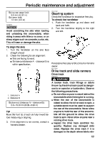
Periodic maintenance and adjustment 10. Rotate the secondary sliding sheave clockwise and push it so that it separates from the secondary fixed sheave. 1. Secondary sliding sheave 2. Secondary fixed sheave 11. Install the V-belt between the secondary sliding and fixed sheaves. 1. V-belt position adjusting bolt 2. Spacer V-belt position More than 1.5 mm (0.06 in) above the edge From 1.5 mm (0.06 in) above the edge to 0.5 mm (0.02 in) below the edge More than 0.5 mm (0.02 in) below the edge Adjustment Remove a spacer. 1. V-belt Not necessary (it is correct). 12. Install the drive guard, and then install the left side cover and the shroud. ESU12106 Add a spacer. Drive chain housing To check the drive chain housing oil level 1. 2. Place the snowmobile on a level surface and apply the parking brake. Remove the shroud and the right side cover. (See page 49 for removal procedures.) Remove the dipstick, wipe it off with a clean rag, and then insert it back into the filler hole. 8. Tighten the V-belt position adjusting bolts. V-belt position adjusting bolt tightening torque: 10 Nm (1.0 m·kgf, 7.2 ft·lbf) 3. 9. Install the V-belt over the primary sheave assembly. 64
-
 1
1 -
2
-
3
-
4
-
5
-
6
-
7
-
8
-
9
-
10
-
11
-
12
-
13
-
14
-
15
-
16
-
17
-
18
-
19
-
20
-
21
-
22
-
23
-
24
-
25
-
26
-
27
-
28
-
29
-
30
-
31
-
32
-
33
-
34
-
35
-
36
-
37
-
38
-
39
-
40
-
41
-
42
-
43
-
44
-
45
-
46
-
47
-
48
-
49
-
50
-
51
-
52
-
53
-
54
-
55
-
56
-
57
-
58
-
59
-
60
-
61
-
62
-
63
-
64
-
 65
65 -
 66
66 -
 67
67 -
 68
68 -
 69
69 -
 70
70 -
 71
71 -
 72
72 -
 73
73 -
 74
74 -
 75
75 -
76
-
77
-
78
-
79
-
80
-
81
-
82
-
83
-
84
-
85
-
86
-
87
-
88
-
89
-
90
-
91
-
92
-
93
-
94
-
95
-
96
-
97
-
98
-
99
-
100
-
101
-
102
-
103
-
104
-
105
-
106
 |
 |
