2008 Yamaha Motorsports Apex M-TX Owners Manual - Page 35
2008 Yamaha Motorsports Apex M-TX Manual

Page 35 highlights
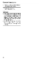
Control functions 1. 2. 3. 4. Special wrench Adjuster length Rim Scale range 4. Tighten the locknut while holding the control rod adjuster in place. Locknut tightening torque: 35 Nm (3.5 m·kgf, 25 ft·lb) ECS00320 CAUTION: When using the special wrench, make sure that it is situated at a right angle to the control rod, and that it is tightly fitted to the locknut or the control rod adjuster. RX10RTR / RX10 MT / RX10MTA 1. Loosen the locknut while holding the control rod adjusting nut. 2. Turn the control rod adjusting nut in direction (a) to increase weight transfer or direction (b) to decrease weight transfer. 1 . Locknut 2. Control rod adjusting nut EWS00170 Never adjust the control rods beyond the maximum range indicated on the rods with red paint. 1 . Red paint area 2. Adjustable range 3. Standard position 29
-
 1
1 -
2
-
3
-
4
-
5
-
6
-
7
-
8
-
9
-
10
-
11
-
12
-
13
-
14
-
15
-
16
-
17
-
18
-
19
-
20
-
21
-
22
-
23
-
24
-
25
-
26
-
27
-
28
-
29
-
 30
30 -
 31
31 -
 32
32 -
 33
33 -
 34
34 -
 35
35 -
 36
36 -
 37
37 -
 38
38 -
 39
39 -
 40
40 -
41
-
42
-
43
-
44
-
45
-
46
-
47
-
48
-
49
-
50
-
51
-
52
-
53
-
54
-
55
-
56
-
57
-
58
-
59
-
60
-
61
-
62
-
63
-
64
-
65
-
66
-
67
-
68
-
69
-
70
-
71
-
72
-
73
-
74
-
75
-
76
-
77
-
78
-
79
-
80
-
81
-
82
-
83
-
84
-
85
-
86
-
87
-
88
-
89
-
90
-
91
-
92
-
93
-
94
-
95
-
96
-
97
-
98
 |
 |
