Panasonic ET-UK20 Geometry Manager Pro Ver.4.0 - Page 72
Line Masking, Upper, Right, Lower, Invert
 |
View all Panasonic ET-UK20 manuals
Add to My Manuals
Save this manual to your list of manuals |
Page 72 highlights
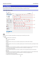
Adjustment and Settings Line Masking Masking ①⑤ ② ③ ④ ① Left When a check mark is entered for enabled. ② Upper When a check mark is entered for enabled. ③ Right When a check mark is entered for is enabled. ④ Lower When a check mark is entered for enabled. ⑤ Invert When a check mark is entered for , masking based on the operation point on the left side of the projected image is , masking based on the operation point at the top of the projected image is , masking based on the operation point on the right side of the projected image , masking based on the operation point at the bottom of the projected image is , the Line Masking area can be inverted between positive and negative. Upper operation point (Blue) Left operation point (Red) Right operation point (Green) Lower operation point (Orange) The operation points at both ends of a side can be moved around the outer circumference (along the four sides) of the image. When an operation point at the center of a side is moved, it can be moved without changing the angle of the straight line that connects the operation points at both ends of the side. When the operation points have been selected, they can also be moved by operating the cursor keys on the keyboard. 72
-
 1
1 -
2
-
3
-
4
-
5
-
6
-
7
-
8
-
9
-
10
-
11
-
12
-
13
-
14
-
15
-
16
-
17
-
18
-
19
-
20
-
21
-
22
-
23
-
24
-
25
-
26
-
27
-
28
-
29
-
30
-
31
-
32
-
33
-
34
-
35
-
36
-
37
-
38
-
39
-
40
-
41
-
42
-
43
-
44
-
45
-
46
-
47
-
48
-
49
-
50
-
51
-
52
-
53
-
54
-
55
-
56
-
57
-
58
-
59
-
60
-
61
-
62
-
63
-
64
-
65
-
66
-
 67
67 -
 68
68 -
 69
69 -
 70
70 -
 71
71 -
 72
72 -
 73
73 -
 74
74 -
 75
75 -
 76
76 -
 77
77 -
78
-
79
-
80
-
81
-
82
-
83
-
84
-
85
-
86
-
87
-
88
-
89
-
90
-
91
-
92
-
93
-
94
-
95
-
96
-
97
-
98
-
99
-
100
-
101
-
102
-
103
-
104
-
105
-
106
-
107
-
108
-
109
-
110
-
111
-
112
-
113
-
114
-
115
-
116
 |
 |
