NEC NP-PA1505UL-B Installation Manual - Page 179
hand, press the left side of the lens lock, Attach the lens cover to the projector.
 |
View all NEC NP-PA1505UL-B manuals
Add to My Manuals
Save this manual to your list of manuals |
Page 179 highlights
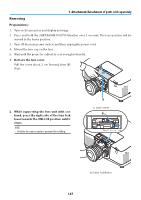
6. Attachment/detachment of parts sold separately 5. With the plate on the lens unit facing up, insert the lens unit into the projector's lens hole. Align the position of the connector and gently insert it as far back as possible. c 6. While supporting the lens unit with your hand, press the left side of the lens lock lever towards the LOCK position until it stops. A clicking sound will confirm that the lens unit is attached to the projector body. The left and right parts of the lens lock lever will open when the lens unit is attached correctly. NOTE: • The lens unit will not lock in place if it is tilted. Move the lens lock lever while the lens unit is still attached to the lens hole. 7. Attach the lens cover to the projector. (1) Leave a gap of about 2 cm when attaching the lens cover. (2) Push it in the direction of the arrow. d c: Plate / d: Connector b b: Lens lock lever a a: Lens cover 146
-
 1
1 -
2
-
3
-
4
-
5
-
6
-
7
-
8
-
9
-
10
-
11
-
12
-
13
-
14
-
15
-
16
-
17
-
18
-
19
-
20
-
21
-
22
-
23
-
24
-
25
-
26
-
27
-
28
-
29
-
30
-
31
-
32
-
33
-
34
-
35
-
36
-
37
-
38
-
39
-
40
-
41
-
42
-
43
-
44
-
45
-
46
-
47
-
48
-
49
-
50
-
51
-
52
-
53
-
54
-
55
-
56
-
57
-
58
-
59
-
60
-
61
-
62
-
63
-
64
-
65
-
66
-
67
-
68
-
69
-
70
-
71
-
72
-
73
-
74
-
75
-
76
-
77
-
78
-
79
-
80
-
81
-
82
-
83
-
84
-
85
-
86
-
87
-
88
-
89
-
90
-
91
-
92
-
93
-
94
-
95
-
96
-
97
-
98
-
99
-
100
-
101
-
102
-
103
-
104
-
105
-
106
-
107
-
108
-
109
-
110
-
111
-
112
-
113
-
114
-
115
-
116
-
117
-
118
-
119
-
120
-
121
-
122
-
123
-
124
-
125
-
126
-
127
-
128
-
129
-
130
-
131
-
132
-
133
-
134
-
135
-
136
-
137
-
138
-
139
-
140
-
141
-
142
-
143
-
144
-
145
-
146
-
147
-
148
-
149
-
150
-
151
-
152
-
153
-
154
-
155
-
156
-
157
-
158
-
159
-
160
-
161
-
162
-
163
-
164
-
165
-
166
-
167
-
168
-
169
-
170
-
171
-
172
-
173
-
 174
174 -
 175
175 -
 176
176 -
 177
177 -
 178
178 -
 179
179 -
 180
180 -
 181
181 -
 182
182 -
 183
183 -
 184
184 -
185
-
186
-
187
-
188
-
189
-
190
-
191
-
192
-
193
-
194
-
195
-
196
-
197
-
198
-
199
-
200
-
201
-
202
-
203
-
204
-
205
-
206
-
207
-
208
-
209
-
210
-
211
-
212
-
213
-
214
-
215
-
216
-
217
-
218
-
219
-
220
-
221
-
222
-
223
-
224
-
225
-
226
 |
 |
