LiftMaster RSL12U RSL12U Troubleshooting Guide Manual - Page 9
Ac Motors
 |
View all LiftMaster RSL12U manuals
Add to My Manuals
Save this manual to your list of manuals |
Page 9 highlights
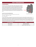
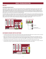
BASIC TROUBLESHOOTING To protect against fire and electrocution: • DISCONNECT power (AC or solar and battery) BEFORE installing or servicing operator. AC MOTORS SYMPTOM: The motor will not run. CHECK THE MOTOR: Disconnect ALL power from operator. Disconnect the gate from the operator. Unplug the motor harness from the board and measure the resistance of the motor. Refer to illustrations. THERMAL SWITCH Measure resistance between: RUN 1 = 600 ohms or less RUN 2 = 600 ohms or less START = 50k ohms or greater THERMAL SWITCH = 0 ohms Unplug motor harness from power board BEFORE measuring. 32 1 65 4 98 7 12 11 10 START RUN 2 RUN 1 12 Blue 11 Yellow 10 Yellow/Black 9 Orange 8 White 7 Red 6 Purple 5 Gray 4 Yellow/Black 3 Purple 2 Gray 1 Black Measure resistance between: 15 to 7 14 to 8 12 to 6 11 to 6 9 to 5 Resistance should be 600 ohms or less There should be continuity between 1 and 4 (Thermal Switch) Unplug motor harness from power board BEFORE measuring. 321 654 987 12 11 10 15 14 13 THERMAL SWITCH 15 Yellow 14 Black 13 Purple 12 Red 11 White 10 Purple 9 Blue 8 Brown 7 Orange 6 Gray 5 Purple 4 Yellow/Black 3 Purple 2 Purple 1 Yellow/Black MODELS CSW200U & SL3000 Red Black Motor shaft should turn easily. J13 J19 J21 J11 J17 J20 MOTOR ID MOTOR RED J14 MOTOR BLUE J10 MOTOR CONTROL CURRENT SENSOR J8 J16 White J7 SWITCH TRANSFORMER J5 COMM J3 120VAC J2 MOTOR WHITE J18 INPUT J1 NEUTRAL OUTLET J12 WHITE J6 BLACK INPUT J4 HOT SWITCH Measure resistance between: Red and Black Black and White Red and White Resistance should be 600 ohms or less. SOLUTION: If the motor measured too much resistance or zero resistance, replace the motor. 8
-
 1
1 -
2
-
3
-
 4
4 -
 5
5 -
 6
6 -
 7
7 -
 8
8 -
 9
9 -
 10
10 -
 11
11 -
 12
12 -
 13
13 -
 14
14 -
15
-
16
-
17
-
18
-
19
-
20
-
21
-
22
-
23
-
24
-
25
-
26
-
27
-
28
-
29
-
30
-
31
-
32
-
33
-
34
-
35
-
36
 |
 |
