LiftMaster RSL12U RSL12U Troubleshooting Guide Manual
LiftMaster RSL12U Manual
 |
View all LiftMaster RSL12U manuals
Add to My Manuals
Save this manual to your list of manuals |
LiftMaster RSL12U manual content summary:
- LiftMaster RSL12U | RSL12U Troubleshooting Guide Manual - Page 1
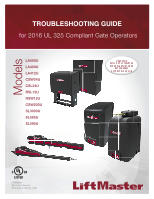
Models TROUBLESHOOTING GUIDE for 2016 UL 325 Compliant Gate Operators LA500U LA400U LA412U CSW24U CSL24U RSL12U RSW12U CSW200U SL3000U SL585U SL595U LiftMaster 845 Larch Avenue Elmhurst, IL 60126-1196 - LiftMaster RSL12U | RSL12U Troubleshooting Guide Manual - Page 2
attempting to install, operate or maintain the operator, you must read and fully understand the manual provided with your operator and follow all safety instructions. • DO NOT attempt repair or service of your gate operator unless you are an Authorized Service Technician. 1 MECHANICAL ELECTRICAL - LiftMaster RSL12U | RSL12U Troubleshooting Guide Manual - Page 3
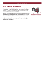
sets across the line to increase performance, safety and accessibility. All LiftMaster UL compliant gate operators will come with external monitored retro-reflective photoelectric sensors (model LMRRU). These operators contain an inherent (internal) entrapment protection system and REQUIRE the - LiftMaster RSL12U | RSL12U Troubleshooting Guide Manual - Page 4
TROUBLESHOOTING MULTI-METERS The image is an example of a generic multimeter. LiftMaster currently has no intended affiliations with this multi-meter manufacturer. This is not an endorsement for this particular meter model circuit of an operator. DC is usually a power source from a battery or the - LiftMaster RSL12U | RSL12U Troubleshooting Guide Manual - Page 5
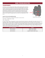
TROUBLESHOOTING voltage created. In commercial gate operators, the secondary side operator. The output rating has nothing to do with the required amount of electricity to make the accessory function. TYPE OF TRANSFORMERS Plug-in Transformer Toroid Transformer Block Transformer MODELS LA400U, RSL12U - LiftMaster RSL12U | RSL12U Troubleshooting Guide Manual - Page 6
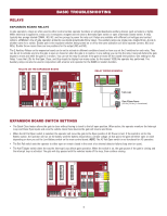
if AC Power is lost. If the switch is set for the Battery option, the operator will run on the battery until the battery drops below a certain voltage. At that point, the gate will either open or close depending on how you set the Low Battery switch on the main control board. NOTE: The AC Fail - LiftMaster RSL12U | RSL12U Troubleshooting Guide Manual - Page 7
BASIC TROUBLESHOOTING To protect against fire and electrocution: • DISCONNECT power (AC or solar and battery) BEFORE installing or servicing operator. CAPACITOR (FOR AC OPERATORS) SYMPTOM: A bad capacitor will cause a motor to hum when trying to run, or stall while it is running. CHECK THE - LiftMaster RSL12U | RSL12U Troubleshooting Guide Manual - Page 8
BASIC TROUBLESHOOTING To protect against fire and electrocution: • DISCONNECT power (AC or solar and battery) BEFORE installing or servicing operator. DC MOTORS SYMPTOM: The motor will not run. CHECK THE MOTOR: Disconnect ALL power from operator. Disconnect the gate from the operator. 12V MOTOR - LiftMaster RSL12U | RSL12U Troubleshooting Guide Manual - Page 9
TROUBLESHOOTING To protect against fire and electrocution: • DISCONNECT power (AC or solar and battery) BEFORE installing or servicing operator. AC MOTORS SYMPTOM: The motor will not run. CHECK THE MOTOR: Disconnect ALL power from operator. Disconnect the gate from the operator Black MODELS CSW200U - LiftMaster RSL12U | RSL12U Troubleshooting Guide Manual - Page 10
protection device is required to operate the gate. ERASE HANDING (AC OPERATORS) 1. To erase the limits, press and hold the OPEN LEFT and OPEN RIGHT buttons simultaneously (5 seconds) until both the OPEN LEFT and OPEN RIGHT LEDs blink rapidly and the operator beeps. 2. Release the buttons and - LiftMaster RSL12U | RSL12U Troubleshooting Guide Manual - Page 11
electrocution: • DISCONNECT power (AC or solar and battery) BEFORE installing or servicing operator. For continued protection against fire: • press and hold the OPEN button until "Er" shows on the display. OPEN, CLOSE, & STOP BUTTONS DIAGNOSTICS DISPLAY The operator will show the code sequence - LiftMaster RSL12U | RSL12U Troubleshooting Guide Manual - Page 12
display as it occurs, then disappear. When servicing of the operator is complete, erase the code history by pressing gate is stopping on may not move in sync. This could cause a problem later on if the hard stop instead of the limit. left (nuisance reversals). Battery overvoltage 40 The operator - LiftMaster RSL12U | RSL12U Troubleshooting Guide Manual - Page 13
it occurs, then disappear. When servicing of the operator is complete, erase the code open connection in the loop. Models LA400U, LA412U, LA500U, RSW12U: Gate will not open. Gate will not close. The operator will beep 2 times with a command. Critically low battery will cause gate to latch open - LiftMaster RSL12U | RSL12U Troubleshooting Guide Manual - Page 14
then disappear. When servicing of the operator is complete, erase the OPEN EYE/EDGE held more than 3 minutes on expansion board Wireless edge triggered more Gate will not move. than 3 minutes Wireless edge loss of monitoring Gate will not move. Wireless edge triggered Gate battery is operational - LiftMaster RSL12U | RSL12U Troubleshooting Guide Manual - Page 15
. When servicing of the operator is complete gate will not close. OPEN EYE/EDGE triggered on the During the open cycle the gate will expansion board reverse for 4 seconds, then stop. The gate will not open. Close input (EYE/EDGE) communication error between primary and secondary operators Open - LiftMaster RSL12U | RSL12U Troubleshooting Guide Manual - Page 16
display as it occurs, then disappear. When servicing of the operator is complete, erase the code history by gate hinges or wheels). When attempting to open or close the • Make sure the gate and gate operator were YES gate, the gate stops and reverses about installed correctly and the gate - LiftMaster RSL12U | RSL12U Troubleshooting Guide Manual - Page 17
. Use LiftMaster low current draw accessories. • Check that the number of gate cycles does not exceed the cycle ratings for the operator and application. • Check that the number of gates cycles corresponds with the solar zones (see below). Refer to your gate operator manual for specific gate cycles - LiftMaster RSL12U | RSL12U Troubleshooting Guide Manual - Page 18
Disconnect all power (AC, solar, battery) to the operator before servicing. NOTE: 10W 12V solar panels are illustrated in the image below. 33AH BATTERIES A To "BATT DC POWER" input on control board Diode B C D 20W 40W 33AH Batteries (in series) 60W 7AH BATTERIES To "BATT DC POWER - LiftMaster RSL12U | RSL12U Troubleshooting Guide Manual - Page 19
12V APPLICATIONS Disconnect all power (AC, solar, battery) to the operator before servicing. NOTE: 10W 12V solar panels are illustrated in the image below. ONE 7AH BATTERY To "BATT DC POWER" input on control board A Diode Solar panels are wired in parallel. ITEMS NEEDED FOR 12V APPLICATIONS - LiftMaster RSL12U | RSL12U Troubleshooting Guide Manual - Page 20
AND SL3000U POWER CONTROL BOARD BIPART DELAY 4 2 6 OPEN LEFT OPEN 8 RIGHT HANDING MODEL CSW200U MODEL SL3000U POWER BOARD (located behind control board) AC POWER power.* Check breaker first, then check wiring coming into operator. The voltage should be 120 Vac. INCOMING POWER 19 - LiftMaster RSL12U | RSL12U Troubleshooting Guide Manual - Page 21
CONTROL BOARD BIPART DELAY 4 2 6 OPEN LEFT OPEN 8 RIGHT HANDING MODEL SL585U CONTROL BOARD POWER BOARD MODEL SL595U CONTROL BOARD POWER BOARD ANTENNA CURRENT first, then check wiring coming into operator. The voltage should be 120, 208, or 240 Vac depending on the application. 20 - LiftMaster RSL12U | RSL12U Troubleshooting Guide Manual - Page 22
CONTROL BOARD BIPART DELAY 4 2 6 OPEN LEFT OPEN 8 RIGHT HANDING MODEL SL585U CONTROL BOARD POWER BOARD MODEL SL595U CONTROL BOARD POWER BOARD JUNCTION BOX first, then check wiring coming into operator. The voltage should be 208, 240, or 480 Vac depending on the application. NCOMING - LiftMaster RSL12U | RSL12U Troubleshooting Guide Manual - Page 23
refer to the Solar Troubleshooting section. Solar Panels 10W minimum - 30W maximum, wired in parallel Battery 12V 7AH Battery 12V 7AH Red Black Black 10W 12V 2 Check the batteries.* Red Check the battery connections. Make sure there is one 7AH battery, two 7AH batteries wired in paralllel - LiftMaster RSL12U | RSL12U Troubleshooting Guide Manual - Page 24
MODEL LA400U SYMPTOM: Operator does not have power. POWER OUTLET batteries.* Check the battery connections. Make sure two 7AH batteries OR two 33AH batteries are connected in series. Check the voltage coming from each battery by disconnecting the battery from the operator. A fully charged battery - LiftMaster RSL12U | RSL12U Troubleshooting Guide Manual - Page 25
MODEL LA500U SYMPTOM: Operator does not have power. POWER CONTROL batteries.* Check the battery connections. Make sure two 7AH batteries OR two 33AH batteries are connected in series. Check the voltage coming from each battery by disconnecting the battery from the operator. A fully charged battery - LiftMaster RSL12U | RSL12U Troubleshooting Guide Manual - Page 26
CSL24U AND CSW24U SYMPTOM: Operator does not have power. MODEL CSW24U POWER MODEL CSL24U CONTROL BOARD CONTROL BOARD OUTLET HOUSING OUTLET HOUSING BATTERIES BATTERIES TRANSFORMER and BRIDGE RECTIFIER located on chassis, behind the electrical box. TRANSFORMER and BRIDGE RECTIFIER located - LiftMaster RSL12U | RSL12U Troubleshooting Guide Manual - Page 27
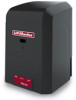
MODELS RSL12U AND RSW12U SYMPTOM: Operator does not have power. POWER * (Back of batteries.* Check the battery connections. Make sure one 7AH battery OR one 33AH battery is connected. Check the voltage coming from each battery by disconnecting the battery from the operator. A fully charged battery - LiftMaster RSL12U | RSL12U Troubleshooting Guide Manual - Page 28
controlling MyQ devices (e.g. gate operator or light control). Does Internet Gateway connect to an existing residential or commercial network? The Internet Gateway UDP) ports need to be opened in our firewall? The Internet network? The Internet Gateway does not support a ping response. Can a static - LiftMaster RSL12U | RSL12U Troubleshooting Guide Manual - Page 29
successful. How to use the RESET button to put a MyQ Gate Operator into programming / learn mode when the gate is closed: 1. Ensure the gate is closed. 2. Give the gate operator an OPEN command. 3. Within 30 seconds, when the gate is at the open limit, press and release the RESET button 3 times (on - LiftMaster RSL12U | RSL12U Troubleshooting Guide Manual - Page 30
, a LiftMaster Gate Operator or light control to a MyQ® account, please review the troubleshooting topics below. CONNECTION ISSUES PROBLEM If the an IP address (e.g. MAC address filtering, firewall settings). • Review the router's settings and manual. • Router must be set to DHCP to provide an - LiftMaster RSL12U | RSL12U Troubleshooting Guide Manual - Page 31
on the gate operator cover along with the installation manual, user guide and quick start guide. • MyQ-Enabled devices communicate using a 900 MHz radio signal. Electronic devices in the same area of the Internet Gateway or MyQ devices may create a range issue. Some troubleshooting options include - LiftMaster RSL12U | RSL12U Troubleshooting Guide Manual - Page 32
devices communicate using a 900 MHz radio signal. Electronic devices in the same area of the Internet Gateway or MyQ-Enabled Gate Operator may create a range issue. Some troubleshooting options include powering down or relocating other 900 MHz products (900 MHz cordless phone, etc.) in the area of - LiftMaster RSL12U | RSL12U Troubleshooting Guide Manual - Page 33
the Internet Gateway by powering off and back on. The Internet Gateway will need to be unplugged to power off. • If you continue to experience a problem, contact the LiftMaster Technical Service Center at 800.528.2806. * A MyQ-Enabled Gate Operator is considered a device. 32 - LiftMaster RSL12U | RSL12U Troubleshooting Guide Manual - Page 34
an outlet with power. • Operate device manually. • If the device responds, remove the device from the account. Add the device back to the account. If the device does not respond, the device may need to be replaced or serviced. • Contact a local dealer or LiftMaster Technical Service Center at 800 - LiftMaster RSL12U | RSL12U Troubleshooting Guide Manual - Page 35
network switch: MANUFACTURER TRENDnet MODEL 5-Port-10/100Mbps TE100-S5 SONICWALL® FIRE WALL PROBLEM The performance issues listed below app. • Manual operation by a MyQ device may not change status on the MyQ app (gate operator is closed by pressing the remote control, but app shows gate open). • - LiftMaster RSL12U | RSL12U Troubleshooting Guide Manual - Page 36
PAS002 845 Larch Avenue Elmhurst, Illinois 60126-1196 LiftMaster.com © 2015, LiftMaster - All Rights Reserved
-
 1
1 -
 2
2 -
 3
3 -
 4
4 -
 5
5 -
 6
6 -
 7
7 -
8
-
9
-
10
-
11
-
12
-
13
-
14
-
15
-
16
-
17
-
18
-
19
-
20
-
21
-
22
-
23
-
24
-
25
-
26
-
27
-
28
-
29
-
30
-
31
-
32
-
33
-
34
-
35
-
36
 |
 |
LiftMaster
845 Larch Avenue
Elmhurst, IL 60126-1196
LA500U
LA400U
LA412U
CSW24U
CSL24U
RSL12U
RSW12U
CSW200U
SL3000U
SL585U
SL595U
TROUBLESHOOTING GUIDE
Models
for 2016 UL 325 Compliant Gate Operators