LiftMaster RSL12U RSL12U Installation Manual
LiftMaster RSL12U Manual
 |
View all LiftMaster RSL12U manuals
Add to My Manuals
Save this manual to your list of manuals |
LiftMaster RSL12U manual content summary:
- LiftMaster RSL12U | RSL12U Installation Manual - Page 1
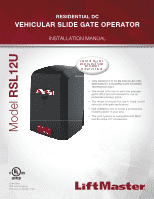
Model RSL12U RESIDENTIAL DC VEHICULAR SLIDE GATE OPERATOR INSTALLATION MANUAL • THIS PRODUCT IS TO BE INSTALLED AND SERVICED BY A TRAINED GATE SYSTEMS TECHNICIAN ONLY. • This model is for use on vehicular passage gates ONLY and not intended for use on pedestrian passage gates. • This model is - LiftMaster RSL12U | RSL12U Installation Manual - Page 2
CODES 30 CONTROL BOARD LEDS 33 TROUBLESHOOTING CHART 34 APPENDIX 36 DUAL GATE SETTINGS 36 SOLAR PANEL(S 37 LIMIT SETUP WITH A REMOTE CONTROL 41 WIRING DIAGRAM 42 REPAIR PARTS 43 ACCESSORIES 44 WARRANTY 46 SAFETY SAFETY SYMBOL AND SIGNAL WORD REVIEW When you see these Safety - LiftMaster RSL12U | RSL12U Installation Manual - Page 3
the gate operator. Failure to adjust and retest the gate operator properly can increase the risk of INJURY or DEATH. • Use the emergency release ONLY when the gate is not moving. • KEEP GATES PROPERLY MAINTAINED. Read the owner's manual. Have a qualified service person make repairs to gate hardware - LiftMaster RSL12U | RSL12U Installation Manual - Page 4
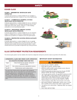
• Photoelectric Sensors • Screen Mesh • Vertical Posts • Instructional and Precautionary Signage 4. Install the gate operator only when: a. The operator is appropriate for the construction and the usage class of the gate. b. All openings of a horizontal slide gate are guarded or screened from the - LiftMaster RSL12U | RSL12U Installation Manual - Page 5
in the horizontal plane parallel to the roadway, between a fixed stationary object nearest the roadway, (such as a gate support post) and the gate frame when the gate is in either the fully open position or the fully closed position, shall not exceed 2 1/4 inches (57 mm), refer to ASTM F2200 for - LiftMaster RSL12U | RSL12U Installation Manual - Page 6
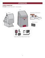
INTRODUCTION CARTON INVENTORY NOT SHOWN: Documentation Packet, Chain #41 - 30 feet, Eye Bolt Kit Cover Operator Warning Signs (2) and Warranty Card Battery 12 Vdc 7AH LiftMaster Monitored Retro-Reflective Photoelectric Sensor 5 - LiftMaster RSL12U | RSL12U Installation Manual - Page 7
INTRODUCTION OPERATOR SPECIFICATIONS This model is intended for use in vehicular slide gate applications: Usage Classification Main AC Supply System Operating Voltage Accessory Power Solar Power Max Maximum Gate Weight Maximum Gate Travel Distance Maximum Gate Travel Speed Maximum Daily Cycle Rate - LiftMaster RSL12U | RSL12U Installation Manual - Page 8
and installed according to ASTM F2200 standards (refer to page 4). Gate must fit specifications of operator (refer to specifications). VEHICLE LOOPS The vehicle loops allow the gate to stay open when vehicles are obstructing the gate path. Suggested for vehicles 14 feet (4.27 m) or longer. Vehicle - LiftMaster RSL12U | RSL12U Installation Manual - Page 9
the risk of entrapment or obstruction exists at either the opening or closing direction. Care shall be exercised to reduce the gate is still moving. Any gap between the gate and a fixed object such as a wall, pillar, column or the operator itself larger than 2 1/4 inches must be filled. SINGLE GATE - LiftMaster RSL12U | RSL12U Installation Manual - Page 10
wear protective gloves and eye protection when changing the battery or working around the battery compartment. TYPES OF INSTALLATIONS STANDARD INSTALLATION Operator Gate Rail Stop (Inside Property) REAR INSTALLATION Operator Gate Rail Stop Gate Rail Stop (Inside Property) Gate Rail Stop 9 - LiftMaster RSL12U | RSL12U Installation Manual - Page 11
24" (61 cm) 24" (61 cm) (Pad) (conduit) REAR INSTALLATION 1. The gate operator should be installed near the back of the gate in the OPEN position. Lay out the concrete pad. 2. Install the electrical conduit. 3. Pour a concrete pad (reinforced concrete is recommended). 1/2" (1.8 cm) (conduit - LiftMaster RSL12U | RSL12U Installation Manual - Page 12
INSTALLATION STEP 2 INSTALL THE OPERATOR Attach the operator to the concrete pad with appropriate fasteners. The gate operator should be installed near the front roller of the gate or near the back of the gate (in the OPEN position). The space between the gate and the output sprocket must be a - LiftMaster RSL12U | RSL12U Installation Manual - Page 13
THE CHAIN DO NOT run the operator until instructed. STANDARD INSTALLATION 1. Manually open the gate and line up the front bracket so the chain will be level with the idler pulley and parallel to the ground. Weld the front bracket in this position. 2. Manually close the gate and line up the rear - LiftMaster RSL12U | RSL12U Installation Manual - Page 14
to test entrapment protection devices monthly. Use only LiftMaster approved entrapment protection devices (refer to the accessory page). NON-CONTACT SENSORS If the photoelectric sensor beam gets blocked while the gate is moving, the gate will stop and reverse. The gate will not be able to travel in - LiftMaster RSL12U | RSL12U Installation Manual - Page 15
will function. Refer to the specific entrapment protection device manual for more information. These entrapment protection device inputs sensed during gate closing the gate will open to the full open position and resets the Timer-to-Close. This input will be disregarded during gate opening. CLOSE - LiftMaster RSL12U | RSL12U Installation Manual - Page 16
be returned to service. • Disconnect power at the fuse box BEFORE proceeding. Operator MUST be properly operator requires one 7AH battery (provided) or one 33AH battery. The 33AH application requires the 33AH wire harness (Model K94-37236). SOLAR APPLICATIONS: For solar applications refer to Solar - LiftMaster RSL12U | RSL12U Installation Manual - Page 17
wire nut. 9. Replace the junction box cover. Ensure the wires are not pinched. 10. Plug in the transformer. 11. Turn ON AC power to the operator. OPERATOR POWER SOURCE DIRECT PLUG-IN TRANSFORMER (120 VAC) Wire Gauge 14 1150 feet (351 m) Wire Gauge 12 1850 feet (564 m) Wire Gauge 10 2950 feet - LiftMaster RSL12U | RSL12U Installation Manual - Page 18
6. Plug in the transformer. Red (+) J15 Plug (solar wires) Black (-) 7AH Battery To use a 33AH battery in place of the 7AH battery, follow the instructions below. The 33AH application requires the 33AH wire harness (Model K94-37236). 33AH BATTERY 1. Unplug the transformer. 2. Unplug the J15 plug - LiftMaster RSL12U | RSL12U Installation Manual - Page 19
wireless communication simultaneously. Wired dual gate applications will have a longer battery standby time than wireless applications. WIRELESS DUAL GATES TO ACTIVATE THE WIRELESS FEATURE: 1. Choose an operator to be the network primary operator. All wireless accessories will need to be programmed - LiftMaster RSL12U | RSL12U Installation Manual - Page 20
, solenoid lock, or decorative overlay would require one gate to close before the other. The operator with the LOCK/BIPART DELAY switch ON will delay from the close limit when opening and be the first to close from the open limit. SLIDE GATE APPLICATIONS: Not applicable, set to OFF. • SYNCHRONIZED - LiftMaster RSL12U | RSL12U Installation Manual - Page 21
INSTALLATION STEP 8 INSTALL THE COVER 1. Slide the cover over the operator. 2. Align the hole in the cover with the threaded hole in the operator's chassis and secure the cover with the provided 5/16-18 screw. The basic installation is complete. 5/16-18 Screw 20 - LiftMaster RSL12U | RSL12U Installation Manual - Page 22
the limits will have to be set for each operator. The gate MUST be attached to the operator before setting the limits and force. For slide gate applications the limits MUST be set at least four feet apart. 1. Press and release the SET OPEN and SET CLOSE buttons simultaneously to enter limit setting - LiftMaster RSL12U | RSL12U Installation Manual - Page 23
any adjustments are made, test the operator: 1. Open and close the gate with the test buttons, ensuring that the gate 1 is stopping at the proper open and close limit positions. 2. Place a solid object between the open gate and a rigid structure. Ensure that the gate, the solid object, and the - LiftMaster RSL12U | RSL12U Installation Manual - Page 24
Timer-to-Close can be set to close the gate. PROGRAMMING STEPS 1. Press and release the LEARN button (operator will beep and green XMITTER LED will light). NOTE: The operator will time out of programming mode after 30 seconds. 2. Press the OPEN button. 3. Press the remote control button that you - LiftMaster RSL12U | RSL12U Installation Manual - Page 25
internet enabled computer or smartphone to add devices. The LiftMaster Internet Gateway will stay in learn mode for three minutes. 6. Ensure gate is closed. 7. Give the operator an OPEN command. 8. Within 30 seconds, when the gate is at the open limit press and release the reset button 3 times (on - LiftMaster RSL12U | RSL12U Installation Manual - Page 26
"SL" followed by a "12" which indicates the operator type as RSL12U. The firmware version will show after the operator type, example "1.2". 12 BACKDRIVE Switch: Set to MANUAL will allow the gate to be manually pushed open or closed if there is a loss of AC and battery power. Set to SECURE makes the - LiftMaster RSL12U | RSL12U Installation Manual - Page 27
allow the gate to be opened and closed manually. To resume normal operation press the reset switch to NORMAL OPERATION. OPERATOR ALARM If minutes the operator will beep. The operator alarm will beep 3 times with a command if the battery is low. When the inherent force of the operator (RPM/current - LiftMaster RSL12U | RSL12U Installation Manual - Page 28
ACCESSORY WIRING EXTERNAL CONTROL DEVICES EXIT (2 Terminals) This input is a soft open command (maintained switch does not override external safeties and does not reset alarm condition). Used for exit probe, telephone entry, external exit loop detector, or any device that would command the gate to - LiftMaster RSL12U | RSL12U Installation Manual - Page 29
VDC, MAX 500 mA (4 Terminals) • SWITCHED: Switched ON with gate motion (stays on 5 seconds after motion). • UNSWITCHED: 12 Vdc voltage out to power accessories, always ON. 28 (main control board) Three Button Control Station Open Close Stop Com N.C. Fire Dept Com Fire Department (main control - LiftMaster RSL12U | RSL12U Installation Manual - Page 30
ONLY LiftMaster part 29-NP712 for replacement batteries. • SAVE THESE INSTRUCTIONS. • ALWAYS wear protective gloves and eye protection when changing the battery or working around the battery compartment. MAINTENANCE CHART Disconnect all power (AC, solar, battery) to the operator before servicing - LiftMaster RSL12U | RSL12U Installation Manual - Page 31
TROUBLESHOOTING To protect against fire and electrocution: • DISCONNECT power (AC or solar and battery) BEFORE installing or servicing operator. press and hold the OPEN button until "Er" shows on the display. OPEN, CLOSE, & STOP BUTTONS DIAGNOSTICS DISPLAY The operator will show the code - LiftMaster RSL12U | RSL12U Installation Manual - Page 32
Failure or missing loop (SHORT or OPEN - LiftMaster Plug-in Loop Detector only) Check loop wiring throughout connection. May be a short in the loop, or an open connection in the loop. Replace batteries in wireless edge. Gate unbalance detected. Make sure the gate is installed on a level surface and - LiftMaster RSL12U | RSL12U Installation Manual - Page 33
Close input (EYE/EDGE) communication fault from other operator Open input (EYE/EDGE) communication fault from other operator Check inputs and communication method between operators, either wired bus or radio. Ensure operator is powered. May have to erase the wireless communication and reprogram - LiftMaster RSL12U | RSL12U Installation Manual - Page 34
single entrapment) FASTEST BLINK (8 The operator is in E2 (double blinks per second) entrapment) BATT LOW OFF No battery error ON Battery low BLINK (1 blink per second) Battery critically low ACC PWR OFF OVLD ON OFF state Accessory overload protector opened SBC INPUT FIRE DEPT INPUT EXIT - LiftMaster RSL12U | RSL12U Installation Manual - Page 35
TROUBLESHOOTING CHART SYMPTOM POSSIBLE CAUSES SOLUTIONS Operator does not a) No power to control board a) Check AC and battery power run and error code b) Open fuse b) Check fuses display not on. c) If on battery power only, low or dead batteries c) Charge batteries by AC or solar - LiftMaster RSL12U | RSL12U Installation Manual - Page 36
shut off alarm and reset the operator. a) Check if AC power is available. If no AC power, then running on batteries and battery voltage must be 11.5 Vdc or higher. Charge batteries by AC or solar power or replace batteries On dual-gate system, incorrect gate opens first or closes first. Alarm beeps - LiftMaster RSL12U | RSL12U Installation Manual - Page 37
a) Add more solar panels b) Reduce the accessory power draw by using LiftMaster low power accessories c) Use batteries with higher amp hour (AH) rating APPENDIX DUAL GATE SETTINGS NOTE: We recommend that all accessories and board configurations are set on the primary operator. MAIN CONTROL BOARD - LiftMaster RSL12U | RSL12U Installation Manual - Page 38
. We recommend LiftMaster low power draw accessories to minimize power draw, refer to accessory page. NOTE: Input solar power is 12 Vdc at 30 watts maximum. The solar panel(s) must be located in an open area clear of obstructions and shading for the entire day. The gate operator is not supported in - LiftMaster RSL12U | RSL12U Installation Manual - Page 39
STEP 6 continued... SOLAR PANEL(S) SOLAR USAGE GUIDE APPENDIX Typical System Standby Battery Current Consumption (mA) System voltage Main board with no radios programmed One or more LiftMaster® remote controls programmed MyQ® device or wireless dual gate programmed Expansion board Per loop - LiftMaster RSL12U | RSL12U Installation Manual - Page 40
the battery is not being charged. TIPS: • Tall trees or buildings that do not shade the solar panel(s) in the summer could shade the solar panel solar panel(s) can be located up to 100 feet (30.48 m) from the operator using #16 AWG wire in any direction, including elevating it. • DO NOT install solar - LiftMaster RSL12U | RSL12U Installation Manual - Page 41
Mounted Panel Must Face South Mounting Surface WIRE THE SOLAR PANELS 1. Locate the J15 plug on the control board and unplug it from the control board (it will not be used). 33AH Battery 2. Set the new 33AH battery in the operator. 3. Route the battery wires (the longer set of wires) from the - LiftMaster RSL12U | RSL12U Installation Manual - Page 42
Press and release the CLOSE button on the remote control again to set the close limit. 8. Cycle the gate open and close. This automatically sets the force. When limits are set properly the operator will automatically exit limit setting mode. ADJUST THE LIMITS If the limits have already been set the - LiftMaster RSL12U | RSL12U Installation Manual - Page 43
WIRING DIAGRAM Field Wiring Edge Edge To protect against fire and electrocution: • DISCONNECT power (AC or solar and battery) BEFORE installing or servicing operator. For continued protection against fire: • Replace ONLY with fuse of same type and rating. Antenna Coaxial Antenna Cable - LiftMaster RSL12U | RSL12U Installation Manual - Page 44
NP712 Battery, 7AH, 12 Vdc K74-30762 Two 7AH batteries K94-37267 Battery Harness (for 7AH batteries) K94-37236 Battery Harness (for 33AH batteries) K1A6408 K77-36541 Chassis K73-37060 Main Board with heat sink K1D8389-1CC Operator Cover with labels K77-37855 (Burgundy) K77-37857 (Gray) - LiftMaster RSL12U | RSL12U Installation Manual - Page 45
ACCESSORIES ENTRAPMENT PROTECTION LIFTMASTER MONITORED THROUGH BEAM PHOTOELECTRIC SENSOR Model LMTBU LIFTMASTER MONITORED RETRO-REFLECTIVE PHOTOELECTRIC SENSOR Model LMRRU and CPS-RPEN4GM LIFTMASTER COMMERCIAL PROTECTOR SYSTEM® Models CPS-UN4 and CPS-UN4G LIFTMASTER MONITORED WIRELESS EDGE KIT ( - LiftMaster RSL12U | RSL12U Installation Manual - Page 46
inside control box. LiftMaster low power accessory. Model LD7LP VEHICLE SENSING PROBE The vehicle sensing probe is buried in the ground and can detect a car as it approaches and will then open the gate. Model CP3 MOUNTING STAND For Model RSL Slide. Ideal to raise slide operator higher above the - LiftMaster RSL12U | RSL12U Installation Manual - Page 47
OF BATTERIES. THIS LIMITED WARRANTY DOES NOT COVER ANY PROBLEMS WITH, OR RELATING TO, THE GATE OR GATE HARDWARE, INCLUDING BUT NOT LIMITED TO THE GATE SPRINGS, GATE ROLLERS, GATE ALIGNMENT OR HINGES. THIS LIMITED WARRANTY ALSO DOES NOT COVER ANY PROBLEMS CAUSED BY INTERFERENCE. ANY SERVICE CALL - LiftMaster RSL12U | RSL12U Installation Manual - Page 48
01-37839C COLOR 845 Larch Avenue Elmhurst, Illinois 60126-1196 LiftMaster.com © 2015, LiftMaster - All Rights Reserved
-
 1
1 -
 2
2 -
 3
3 -
 4
4 -
 5
5 -
 6
6 -
 7
7 -
8
-
9
-
10
-
11
-
12
-
13
-
14
-
15
-
16
-
17
-
18
-
19
-
20
-
21
-
22
-
23
-
24
-
25
-
26
-
27
-
28
-
29
-
30
-
31
-
32
-
33
-
34
-
35
-
36
-
37
-
38
-
39
-
40
-
41
-
42
-
43
-
44
-
45
-
46
-
47
-
48
 |
 |
RESIDENTIAL DC
VEHICULAR SLIDE GATE OPERATOR
INSTALLATION MANUAL
LiftMaster
845 Larch Avenue
Elmhurst, IL 60126-1196
Model
RSL12U
•
THIS PRODUCT IS TO BE INSTALLED AND
SERVICED BY A TRAINED GATE SYSTEMS
TECHNICIAN ONLY.
•
This model is for use on vehicular passage
gates ONLY and not intended for use on
pedestrian passage gates.
•
This model is intended for use in Class I and II
vehicular slide gate applications.
•
Visit LiftMaster.com to locate a professional
installing dealer in your area.
•
This gate operator is compatible with MyQ
®
and Security+ 2.0
®
accessories.