LiftMaster 61LM Owners Manual - Page 164
Service Information Toll Free Number
 |
View all LiftMaster 61LM manuals
Add to My Manuals
Save this manual to your list of manuals |
Page 164 highlights
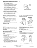
Install Jumper Wire for 3-Way Switch Applications Only, Figure 6: • Remove switch plate and screws from second 3-way switch. Pull switch from junction box. • Identify wire #1 previously connected to the red control wire in Figure 4. Loosen the terminal screw holding wire #1 just enough to install one end of the jumper wire. Retighten the screw. • Loosen screw at either of the two other terminals and install other end of jumper wire. Retighten screw. • Reinstall switch and turn power back on. Turn Light Control on by moving the slide lever to ON position. Try operating the light using the second (remote 3-way) switch. • If light does not operate, TURN POWER OFF at fuses or circuit breaker and remove the remote 3-way switch. • Rewire the jumper to go from the wire #1 terminal to the other terminal. • Reinstall switch and turn power back on. Both the remote switch and the Light Control should now be able to control the light. Set Receiver to Match Remote Control(s) Code: Turn on the power to circuit at fuse box or circuit breaker. Select a remote control push button to operate the Light Control. • Press and HOLD the remote control push button. • Then press and release the "Smart" button on the receiver with a pen or pencil tip. The adjacent green indicator light will FLASH once. Release the remote control push button. Code setting is complete. Snap actuator back on receiver. NOTE: If the remote control push button is not held down until the receiver indicator light flashes, the light control has not accepted the code. TO TEST: Press the actuator. The light should turn on. Press again and the light should turn off. Press remote control push button. The light should turn on. Press again and the light should turn off. Remote control range will vary depending on your house and wiring construction. Metal lath, foil-backed insulation or aluminum siding will reduce range. After installation is complete, test remote control operation at various locations within your home for convenience and range. If the light does not operate, check to be sure: • The power is ON. Check the fuse box or circuit breaker. • The light bulb is "good". • The receiver is firmly connected to the power supply and the slide bar is in the ON position. • The electrical wiring is correct. Review the wiring instructions for Single/3-Way Switch. • You are pressing the remote control push button selected to operate the light control. • The remote control has power. NOTE: Test light on the remote control should glow when push button is pressed. (Battery changing information is included in instructions packed with your remote control.) Figure 6 Connect Jumper Wire Wire #1 Remote Switch (3-Way) Move jumper wire to other terminal if this switch does not turn light on. If the "Smart" button is pressed and held until the indicator light alongside goes out (approximately 6 seconds), all memorized codes will be erased. Receiver Multi-Function Remote Control Model 63 LM O N Indicator Light PROGRAM "Smart" Button Select a remote control push button to operate receiver CAUTION: To avoid electric shock, move the slide switch to the OFF position whenever it is necessary to change a light bulb. NOTE: If you use less than a 40 Watt bulb, the lamp may glow dimly when OFF. This is normal. If two or more light products are installed, they must be located at least 10 feet apart to prevent electronic interference. No user serviceable parts. The Multi-Function remote control can also operate the Plug-In Light Control Accessory, Model 742LM. Multi-Function Remote Control Plug-In Light Control SERVICE INFORMATION TOLL FREE NUMBER: 1-800-528-9131 114A1590E © 1994, The Chamberlain Group, Inc. All Rights Reserved Printed in Mexico
-
 1
1 -
2
-
3
-
4
-
5
-
6
-
7
-
8
-
9
-
10
-
11
-
12
-
13
-
14
-
15
-
16
-
17
-
18
-
19
-
20
-
21
-
22
-
23
-
24
-
25
-
26
-
27
-
28
-
29
-
30
-
31
-
32
-
33
-
34
-
35
-
36
-
37
-
38
-
39
-
40
-
41
-
42
-
43
-
44
-
45
-
46
-
47
-
48
-
49
-
50
-
51
-
52
-
53
-
54
-
55
-
56
-
57
-
58
-
59
-
60
-
61
-
62
-
63
-
64
-
65
-
66
-
67
-
68
-
69
-
70
-
71
-
72
-
73
-
74
-
75
-
76
-
77
-
78
-
79
-
80
-
81
-
82
-
83
-
84
-
85
-
86
-
87
-
88
-
89
-
90
-
91
-
92
-
93
-
94
-
95
-
96
-
97
-
98
-
99
-
100
-
101
-
102
-
103
-
104
-
105
-
106
-
107
-
108
-
109
-
110
-
111
-
112
-
113
-
114
-
115
-
116
-
117
-
118
-
119
-
120
-
121
-
122
-
123
-
124
-
125
-
126
-
127
-
128
-
129
-
130
-
131
-
132
-
133
-
134
-
135
-
136
-
137
-
138
-
139
-
140
-
141
-
142
-
143
-
144
-
145
-
146
-
147
-
148
-
149
-
150
-
151
-
152
-
153
-
154
-
155
-
156
-
157
-
158
-
 159
159 -
 160
160 -
 161
161 -
 162
162 -
 163
163 -
 164
164 -
 165
165 -
 166
166 -
 167
167 -
 168
168 -
 169
169 -
170
-
171
-
172
-
173
-
174
-
175
-
176
-
177
-
178
-
179
-
180
-
181
-
182
-
183
-
184
-
185
-
186
-
187
-
188
-
189
-
190
-
191
-
192
-
193
-
194
-
195
-
196
-
197
-
198
-
199
-
200
-
201
-
202
-
203
-
204
-
205
-
206
-
207
-
208
-
209
-
210
-
211
-
212
-
213
-
214
-
215
-
216
-
217
-
218
-
219
-
220
-
221
-
222
-
223
-
224
-
225
-
226
-
227
-
228
-
229
-
230
-
231
-
232
-
233
-
234
-
235
-
236
-
237
-
238
-
239
-
240
-
241
-
242
-
243
-
244
-
245
-
246
-
247
-
248
-
249
-
250
-
251
-
252
-
253
-
254
-
255
-
256
-
257
-
258
-
259
-
260
-
261
-
262
-
263
-
264
-
265
-
266
-
267
-
268
-
269
-
270
-
271
-
272
-
273
-
274
-
275
-
276
-
277
-
278
-
279
-
280
-
281
-
282
-
283
-
284
-
285
-
286
 |
 |
