Epson C117001-N Service Manual - Page 98
t-lfl, Vm
 |
UPC - 010343816480
View all Epson C117001-N manuals
Add to My Manuals
Save this manual to your list of manuals |
Page 98 highlights
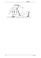
Disassembly and Assembly 3.2.6 Removing the Printer Mechanism This section describes how to remove the printer mechanism. DFX-5000+ Service Manual Because the printer mechanism is large and heavy, you must be careful when you remove it. When you lift or lower the printer mechanism, follow these precautions: Ll Two people are required to remove or install the printer mechanism. Q Use the lift handles (#E656, part number B765111OO1) designed for lifling or lowen"ng the printer mechanism when you remove or install it. U To avoid straining your waist, hands, or feet, place the printer on a low table before following the steps below. 1. Remove the interlock switch assembly. (Refer to Section 3.2.5) 2. I&move the 3 CBS (0) (M4 x 8) screws securing the green and yellow earth cables to the earth plate. There are two screws on the left and one on the right. 3. Disconnect the cables from connectors CN1O, CN7, and CN6 on the left side of the C117 MAIN board assembly. 4. Remove the 4 screws securing the printer mechanism to the lower case. 't((-((lfl, ,, 1!21 I ,Vm p,,l In CBS (0) (M4x8) I SCREWS CBS (0) (M4x8) SCREW 2 SCREWS 2 SCREWS CBS (0) (M4x8) SCREWS Figure 3-28. Removing the Printer Mechanism 3-22 Rev. A
-
 1
1 -
2
-
3
-
4
-
5
-
6
-
7
-
8
-
9
-
10
-
11
-
12
-
13
-
14
-
15
-
16
-
17
-
18
-
19
-
20
-
21
-
22
-
23
-
24
-
25
-
26
-
27
-
28
-
29
-
30
-
31
-
32
-
33
-
34
-
35
-
36
-
37
-
38
-
39
-
40
-
41
-
42
-
43
-
44
-
45
-
46
-
47
-
48
-
49
-
50
-
51
-
52
-
53
-
54
-
55
-
56
-
57
-
58
-
59
-
60
-
61
-
62
-
63
-
64
-
65
-
66
-
67
-
68
-
69
-
70
-
71
-
72
-
73
-
74
-
75
-
76
-
77
-
78
-
79
-
80
-
81
-
82
-
83
-
84
-
85
-
86
-
87
-
88
-
89
-
90
-
91
-
92
-
 93
93 -
 94
94 -
 95
95 -
 96
96 -
 97
97 -
 98
98 -
 99
99 -
 100
100 -
 101
101 -
 102
102 -
 103
103 -
104
-
105
-
106
-
107
-
108
-
109
-
110
-
111
-
112
-
113
-
114
-
115
-
116
-
117
-
118
-
119
-
120
-
121
-
122
-
123
-
124
-
125
-
126
-
127
-
128
-
129
-
130
-
131
-
132
-
133
-
134
-
135
-
136
-
137
-
138
-
139
-
140
-
141
-
142
-
143
-
144
-
145
-
146
-
147
-
148
-
149
-
150
-
151
-
152
-
153
-
154
-
155
-
156
-
157
-
158
-
159
-
160
-
161
-
162
-
163
-
164
-
165
-
166
-
167
-
168
-
169
-
170
-
171
-
172
-
173
-
174
-
175
-
176
-
177
-
178
-
179
-
180
-
181
-
182
-
183
-
184
-
185
-
186
 |
 |
