Epson C117001-N Service Manual - Page 70
Table 2-6. PF Motor Specifications, 3.6 RF Motor Driver Circuit, RF Motor Driver Circuit
 |
UPC - 010343816480
View all Epson C117001-N manuals
Add to My Manuals
Save this manual to your list of manuals |
Page 70 highlights
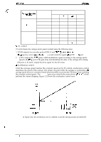
e ,.. ,. ("J DEX-5000+ Sarvice Manual Table 2-6. PF Motor Specifications Oparatfng Phc@ba Specification tkaaoription b Form 4-phase, 200-pole, HB* pulse motor Supply voltage 35 VDC t 6% (applied to the driver circuit) 1 I Internal coil resistance I 2.65 f2 +0.32 Llperphaseat 25°C (77°F) I Frequency 4274 pps~ (normal mode, constant driving): 9.9 ipe"" 2610 pps (middle speed mode, constant driving): 6 ips I Current consumption Driving: 1.95 Aj 0.20A per phase (average) Holding: 0.26 A, 0.02A per phase (average) I * HB = Hybrid * pps = pulses per second ** ips = inches per second 2.3.6 RF Motor Driver Circuit Figure 2-28 shows a block diagram of the RF motor driver circuit, and Table 2-7 provides the RF motor specifications. The RF motor is a stepping motor. The control circuit perlbrms open-loop phase switching control according to the timing data for acceleration mnstant speed, and deceleration. CPU ports PG1O to PG13 output the motor phase switching signals. The control method is not equipped with a hold circuit for changing the motor phase. 'The RF motor rotates when the carriage moves. w TMP96C141 (lCl) PG1O ® PG 11 " ® PG12 ® , PG 13 + ~ PNP Transistor x4 CN; Figure 2-28. RF Motor Driver Circuit Specification Form Supply voltage Internal coil resistance Cunent consumption Frequency Driving method Table 2-7. RF Motor Specifications I i I I Description I I 4-phase, 46-poie, PM pulse motor I 35 VDC * 6% (apptied to the driver circuit) 1 I 150 Q f 13 Q per phase at 25°C (77°F) I Driving: 0.10 A (average) I I ! " s 7 2 0 ~ Constant voltage driving, 2-2 phase drive only I Rev. A 2-31
-
 1
1 -
2
-
3
-
4
-
5
-
6
-
7
-
8
-
9
-
10
-
11
-
12
-
13
-
14
-
15
-
16
-
17
-
18
-
19
-
20
-
21
-
22
-
23
-
24
-
25
-
26
-
27
-
28
-
29
-
30
-
31
-
32
-
33
-
34
-
35
-
36
-
37
-
38
-
39
-
40
-
41
-
42
-
43
-
44
-
45
-
46
-
47
-
48
-
49
-
50
-
51
-
52
-
53
-
54
-
55
-
56
-
57
-
58
-
59
-
60
-
61
-
62
-
63
-
64
-
 65
65 -
 66
66 -
 67
67 -
 68
68 -
 69
69 -
 70
70 -
 71
71 -
 72
72 -
 73
73 -
 74
74 -
 75
75 -
76
-
77
-
78
-
79
-
80
-
81
-
82
-
83
-
84
-
85
-
86
-
87
-
88
-
89
-
90
-
91
-
92
-
93
-
94
-
95
-
96
-
97
-
98
-
99
-
100
-
101
-
102
-
103
-
104
-
105
-
106
-
107
-
108
-
109
-
110
-
111
-
112
-
113
-
114
-
115
-
116
-
117
-
118
-
119
-
120
-
121
-
122
-
123
-
124
-
125
-
126
-
127
-
128
-
129
-
130
-
131
-
132
-
133
-
134
-
135
-
136
-
137
-
138
-
139
-
140
-
141
-
142
-
143
-
144
-
145
-
146
-
147
-
148
-
149
-
150
-
151
-
152
-
153
-
154
-
155
-
156
-
157
-
158
-
159
-
160
-
161
-
162
-
163
-
164
-
165
-
166
-
167
-
168
-
169
-
170
-
171
-
172
-
173
-
174
-
175
-
176
-
177
-
178
-
179
-
180
-
181
-
182
-
183
-
184
-
185
-
186
 |
 |
