Epson C117001-N Service Manual - Page 18
Stapled Area 3, Correct, Form Binding, Area for, Paper with
 |
UPC - 010343816480
View all Epson C117001-N manuals
Add to My Manuals
Save this manual to your list of manuals |
Page 18 highlights
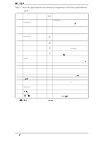
Pfvduct Descfiptkm DEMO(M+ Servke hisnual 7. The binding area must be fiat. Figure 1-17 shows a cross section of the stapled area. NG Figure 1-17. Stapled Area 3 8. Never use forms joined with metal staples. 9. The binding (dots of paste or paper staples) must be outside the printable area. 10. Overlapping multi-part forms must be bound at the top side by spot gluing. The binding must be secure and there should be no spilled giue. Figure 1-18 shows the correct multi-part form binding method. 11. Multi-part firm sheets should be securely bound to each other, and the binding area must not be too large. Paate Figure 1-18. Correct Muiti-part Form Binding Fanfold Paper with a Labal Paper path: Front only Quality: Plain paper Width: 101-406 mm (4 - 16 inches) Total thickness: 0.46 mm (0.018 inches) rruximum Weight: Single Multi-part 4 5 - 70kg(14- 221b) 35- 48kg (11 -15 lb) x n (n < 8), up tothe total thickness No pmling area 'w c.-,.-~'',t\ 13nml 01 A 10 A Figure 1-19. Printabie Area for Fanfoid Paper with a Labei 1-1o Rev. A
-
 1
1 -
2
-
3
-
4
-
5
-
6
-
7
-
8
-
9
-
10
-
11
-
12
-
 13
13 -
 14
14 -
 15
15 -
 16
16 -
 17
17 -
 18
18 -
 19
19 -
 20
20 -
 21
21 -
 22
22 -
 23
23 -
24
-
25
-
26
-
27
-
28
-
29
-
30
-
31
-
32
-
33
-
34
-
35
-
36
-
37
-
38
-
39
-
40
-
41
-
42
-
43
-
44
-
45
-
46
-
47
-
48
-
49
-
50
-
51
-
52
-
53
-
54
-
55
-
56
-
57
-
58
-
59
-
60
-
61
-
62
-
63
-
64
-
65
-
66
-
67
-
68
-
69
-
70
-
71
-
72
-
73
-
74
-
75
-
76
-
77
-
78
-
79
-
80
-
81
-
82
-
83
-
84
-
85
-
86
-
87
-
88
-
89
-
90
-
91
-
92
-
93
-
94
-
95
-
96
-
97
-
98
-
99
-
100
-
101
-
102
-
103
-
104
-
105
-
106
-
107
-
108
-
109
-
110
-
111
-
112
-
113
-
114
-
115
-
116
-
117
-
118
-
119
-
120
-
121
-
122
-
123
-
124
-
125
-
126
-
127
-
128
-
129
-
130
-
131
-
132
-
133
-
134
-
135
-
136
-
137
-
138
-
139
-
140
-
141
-
142
-
143
-
144
-
145
-
146
-
147
-
148
-
149
-
150
-
151
-
152
-
153
-
154
-
155
-
156
-
157
-
158
-
159
-
160
-
161
-
162
-
163
-
164
-
165
-
166
-
167
-
168
-
169
-
170
-
171
-
172
-
173
-
174
-
175
-
176
-
177
-
178
-
179
-
180
-
181
-
182
-
183
-
184
-
185
-
186
 |
 |
