Epson C117001-N Service Manual - Page 101
Attach the, tractor select, to the tractor, as shown in fiontlrear, leoer, sekct
 |
UPC - 010343816480
View all Epson C117001-N manuals
Add to My Manuals
Save this manual to your list of manuals |
Page 101 highlights
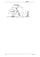
DFX-5000+ Service Manual llsassembty and Assamb& 3.2.7.2 Disassembling the Front/Rear Tractor Select Lever Assembly This section describes how to disassemble the front/rear tractor select lever assembly, including how to remove the RF motor and tractor select sensor. 1. Remove the front/rear tractor select lever assembly. (Refer to Section 3.2.7.1) 2. Remove the 2 CP (PS) (M3 x 6) screws securing the RF motor to the front/rear tractor select lever assembly and remove the motor. Discomect the cable from the black comector on the RF motor. 3. Remove the E ring (#3) securing the front/rear tractor select lever and remove the lever. Remove the E ring (# 3) securing the tractor select cam and remove the mm. 4. Remove the CPS (IW2 x 10) screw securing the tractor select sensor and remove the wnsor. r T&W&" S E L E C T " / -1-HA.G -I-U- -H SA-t,L-tAb -I LEVER LOWER .!? \ 'o L"" / ~~ 1 ! RIBBON FEED MOTOR FRAME ~ RIBBON FEED \ MOTOR m 'a iI 'CP (PS) (M3x6) c"/) Figure 3-33. Disassembling the Tractor Select Lever 5. Using wire cutters, cut the wire band securing the RF motor and tractor select sensor cables to the front/rear tractor select lever assembly. Attach the fiontlrear tractor select leoer to the tractor sekct cam as shown in Figure 3-34. c) Rev. A 3-25
-
 1
1 -
2
-
3
-
4
-
5
-
6
-
7
-
8
-
9
-
10
-
11
-
12
-
13
-
14
-
15
-
16
-
17
-
18
-
19
-
20
-
21
-
22
-
23
-
24
-
25
-
26
-
27
-
28
-
29
-
30
-
31
-
32
-
33
-
34
-
35
-
36
-
37
-
38
-
39
-
40
-
41
-
42
-
43
-
44
-
45
-
46
-
47
-
48
-
49
-
50
-
51
-
52
-
53
-
54
-
55
-
56
-
57
-
58
-
59
-
60
-
61
-
62
-
63
-
64
-
65
-
66
-
67
-
68
-
69
-
70
-
71
-
72
-
73
-
74
-
75
-
76
-
77
-
78
-
79
-
80
-
81
-
82
-
83
-
84
-
85
-
86
-
87
-
88
-
89
-
90
-
91
-
92
-
93
-
94
-
95
-
 96
96 -
 97
97 -
 98
98 -
 99
99 -
 100
100 -
 101
101 -
 102
102 -
 103
103 -
 104
104 -
 105
105 -
 106
106 -
107
-
108
-
109
-
110
-
111
-
112
-
113
-
114
-
115
-
116
-
117
-
118
-
119
-
120
-
121
-
122
-
123
-
124
-
125
-
126
-
127
-
128
-
129
-
130
-
131
-
132
-
133
-
134
-
135
-
136
-
137
-
138
-
139
-
140
-
141
-
142
-
143
-
144
-
145
-
146
-
147
-
148
-
149
-
150
-
151
-
152
-
153
-
154
-
155
-
156
-
157
-
158
-
159
-
160
-
161
-
162
-
163
-
164
-
165
-
166
-
167
-
168
-
169
-
170
-
171
-
172
-
173
-
174
-
175
-
176
-
177
-
178
-
179
-
180
-
181
-
182
-
183
-
184
-
185
-
186
 |
 |
