Dell Latitude 7280 Owners Manual
Dell Latitude 7280 Manual
 |
View all Dell Latitude 7280 manuals
Add to My Manuals
Save this manual to your list of manuals |
Dell Latitude 7280 manual content summary:
- Dell Latitude 7280 | Owners Manual - Page 1
Dell Latitude 7280 Owner's Manual 1.0 Regulatory Model: P28S Regulatory Type: P28S001 May 2020 Rev. A06 - Dell Latitude 7280 | Owners Manual - Page 2
of data and tells you how to avoid the problem. WARNING: A WARNING indicates a potential for property damage, personal injury, or death. © 2020 Dell Inc. or its subsidiaries. All rights reserved. Dell, EMC, and other trademarks are trademarks of Dell Inc. or its subsidiaries. Other trademarks may be - Dell Latitude 7280 | Owners Manual - Page 3
(SIM) card...10 Removing SIM card or SIM card tray...10 Replacing SIM card...10 Base cover...10 Removing base cover...10 Installing base cover...12 Battery...12 Lithium-ion battery precautions...12 Removing battery...12 Installing battery...13 PCIe Solid State Drive (SSD)...13 Removing PCIe SSD...13 - Dell Latitude 7280 | Owners Manual - Page 4
to keyboard tray...42 Palm rest...42 Replacing palm rest ...42 3 System specifications...44 Supported operating systems...44 Processor specifications...44 System specifications...45 Memory specifications...45 Storage specifications...45 Video specifications...45 Audio specifications...45 Battery - Dell Latitude 7280 | Owners Manual - Page 5
...58 POST behavior screen options...59 Manageability...59 Virtualization support screen options...59 Wireless screen options...60 Maintenance screen changing an existing system and/or setup password 62 5 Troubleshooting...63 Enhanced Pre-Boot System Assessment (ePSA) diagnostics 63 Running the - Dell Latitude 7280 | Owners Manual - Page 6
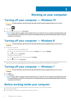
your work surface is flat and clean to prevent the computer cover from being scratched. 2. Turn off your computer. 3. If the computer is connected to a docking device (docked), undock it. 6 Working on your computer - Dell Latitude 7280 | Owners Manual - Page 7
only perform troubleshooting and simple repairs as authorized in your product documentation, or as directed by the online or telephone service and support team. Damage due to servicing that is not authorized by Dell is not covered by your warranty. Read and follow the safety instructions that came - Dell Latitude 7280 | Owners Manual - Page 8
CAUTION: To connect a network cable, first plug the cable into the network device and then plug it into the computer. 3. Connect your computer and all attached devices to their electrical outlets. 4. Turn on your computer. 8 Working on your computer - Dell Latitude 7280 | Owners Manual - Page 9
Table 1. Latitude 7280 - screw size list Component M2.5 x 6 Back cover Battery-3-cell Battery-4-cell SSD module Heat sink module System fan Speaker WWAN card WLAN card Power connector port ESD bracket EDP bracket Touchpad buttons Fingerprint reader LED board Smart card reader cage Keyboard Lock - Dell Latitude 7280 | Owners Manual - Page 10
, if a SIM card is available from the SIM card tray. Replacing SIM card NOTE: You can replace a SIM card only for those systems that are shipped with WWAN module 1. Follow the procedure in Before working inside your computer. 2. To release the base cover: a. Loosen the M2.5 x 6 captive screws (8) - Dell Latitude 7280 | Owners Manual - Page 11
CAUTION: Exercise caution when loosening the screws. Angle the screwdriver to match the head of the screw (front corners on the laptop base cover) to avoid a possible stripped screw head. 3. Lift the base cover from the computer. Disassembly and reassembly 11 - Dell Latitude 7280 | Owners Manual - Page 12
the screw driver to match instructions. • If the battery gets stuck inside your computer as a result of swelling, do not try to release it as puncturing, bending, or crushing a lithium-ion battery can be dangerous. In such an instance, contact Dell technical support for assistance. See www.dell - Dell Latitude 7280 | Owners Manual - Page 13
computer. PCIe Solid State Drive (SSD) Removing PCIe SSD 1. Follow the procedure in Before working inside your computer. 2. Remove the : a. base cover b. battery 3. To remove the PCIe SSD: a. Loosen the M2 x3 captive screw that secure the SSD bracket [1]. b. Remove the SSD bracket [2]. c. Remove the - Dell Latitude 7280 | Owners Manual - Page 14
the bracket is the system is shipped with bracket. 3. Tighten the M2 x 3 screws to secure it the SSD bracket. 4. Install the a. battery b. base cover 5. Follow the procedure in After working iinside your computer. Speaker Removing speaker module 1. Follow the procedure in Before working inside your - Dell Latitude 7280 | Owners Manual - Page 15
speaker cable from the connector on the system board [1]. NOTE: Ensure to unroute the speaker cable from the routing clip. NOTE: Use a plastic scribe to release the cable from the connector. Do not pull the cable as it may result in breakage. b. Un-route the speaker cable from the routing clips - Dell Latitude 7280 | Owners Manual - Page 16
Before working inside your computer. 2. Remove the : a. base cover b. battery 3. To remove the coin cell battery: a. Disconnect the coin cell battery cable from the connector on the system board [1]. b. Lift the coin cell battery to release it from the adhesive [2]. 16 Disassembly and reassembly - Dell Latitude 7280 | Owners Manual - Page 17
After working inside your computer. WWAN card Removing WWAN card 1. Follow the procedure in Before working inside your computer. 2. Remove the : a. base cover b. battery 3. To remove the WWAN card: a. Remove the M2.0 x 3.0 screw that secures the metal bracket to the WWAN card [1]. b. Lift the metal - Dell Latitude 7280 | Owners Manual - Page 18
to the connectors on the WWAN card. 3. Place the metal bracket and tighten the M2.0 x 3.0 screw to secure it to the computer. 4. Install the : a. battery b. base cover 5. Follow the procedure in After working inside your computer. NOTE: The IMEI number can also be found on the WWAN card. WLAN card - Dell Latitude 7280 | Owners Manual - Page 19
on the WLAN card. 3. Place the metal bracket and tighten the M2.0 x 3.0 screw to secure it to the computer. 4. Install the .: a. battery b. base cover 5. Follow the procedure in After working inside your computer. Memory module Removing memory module 1. Follow the procedure in Before working inside - Dell Latitude 7280 | Owners Manual - Page 20
sink assembly comprises of heat sink and the system fan. 1. Follow the procedure in Before working inside your computer. 2. Remove the : a. base cover b. battery 3. To remove the heat sink assembly: NOTE: To identify the number of screws, see screw list. a. Disconnect the fan cable from the system - Dell Latitude 7280 | Owners Manual - Page 21
the fan cable to the connector on the system board. 5. Install the : a. battery b. base cover 6. Follow the procedure in After working inside your computer. Power connector port Removing power connector port 1. Follow the procedure in Before working inside your computer. 2. Remove the : a. base - Dell Latitude 7280 | Owners Manual - Page 22
Remove the M2.0x3.0 screw (1) to release the metal bracket on the power connector port [2]. c. Lift the metal bracket from the computer [3]. d. the power connector port from the computer [4]. Installing power connector port 1. Install the power connector port into the slot on the computer. 2. Place - Dell Latitude 7280 | Owners Manual - Page 23
a. base cover b. battery 3. To remove the LED board: a. Disconnect the LED cable from the LED board [1]. CAUTION: Avoid pulling the cable as it would result in breaking the cable connector. Instead, use a scribe to release the LED cable from its connector. b. Unroute the LED cable from the routing - Dell Latitude 7280 | Owners Manual - Page 24
working inside your computer. 2. Remove the: a. base cover b. battery c. PCIe SSD card 3. To disconnect the smart card cable: a. cable that is affixed to the touchpad module [2]. NOTE: Ensure to pull gently to release it with adhesive tape. 4. To remove the smart card cage: NOTE: To identify - Dell Latitude 7280 | Owners Manual - Page 25
to the computer. 3. Affix the smart card cable and connect it to the connector on the computer . 4. Install the: a. PCIe SSD card b. battery c. base cover 5. Follow the procedure in After working inside your computer. Touchpad Removing touchpad buttons board 1. Follow the procedure in Before working - Dell Latitude 7280 | Owners Manual - Page 26
cable from the touchpad board [1]. NOTE: The touchpad buttons board cable is below the smart card cable. Ensure to lift the latch, to release the touchpad button board cable. b. Remove M2.0 x 2.5 screws (2) that secure the touchpad buttons board [2]. NOTE: To identify the screws, see screw list - Dell Latitude 7280 | Owners Manual - Page 27
computer. Display Assembly Removing display assembly-with Touch 1. Follow the procedure in Before working inside your computer. 2. Remove the: a. base cover b. battery c. WLAN card d. WWAN card NOTE: To identify the number of screws, see screw list 3. To remove the display assembly: Disassembly and - Dell Latitude 7280 | Owners Manual - Page 28
a. Un route the WLAN and WWAN cables from the routing channels [1]. b. Remove the M2.0 x 5.0 screws that secures the eDP bracket [2]. c. Lift the eDP bracket from the eDP cable [3]. d. Lift the eDP cable to disconnect it from the connector on the system board [4]. e. Un route the eDP cable from the - Dell Latitude 7280 | Owners Manual - Page 29
tighten the M2.0 x 5.0 screws. 7. Route the WLAN and WWAN cables through the routing channels. 8. Install the: a. WLAN card b. WWAN card c. battery d. base cover 9. Follow the procedure in After working inside your computer. Installing display bezel NOTE: The display bezel installation procedure is - Dell Latitude 7280 | Owners Manual - Page 30
the procedure in Before working inside your computer. 2. Remove the following components: a. base cover b. battery c. WLAN card d. WWAN card e. display assembly 3. Slide hinge cap from left to the right to release and remove the display hinge cap from the display panel. Installing the display hinge - Dell Latitude 7280 | Owners Manual - Page 31
g. hinge caps 3. To remove the display panel: a. Remove the two (M2.0 x 2.0) screws on the panel [1]. b. Lift up the top edge of the display panel [2] and flip the display panel over. c. Peel off the display connector adhesive strip from the display panel [1] d. Peel off the Mylar tape securing the - Dell Latitude 7280 | Owners Manual - Page 32
f. Remove the display panel. 32 Disassembly and reassembly - Dell Latitude 7280 | Owners Manual - Page 33
Flip the display panel over and slide the display panel towards the system. 5. Replace the two (M2.0 x 2.0) screws on the panel 6. Install the: a. Bezel b. Hinge Cap c. display assembly d. WLAN card e. WWAN card f. battery g. base cover 7. Follow the procedure in After working inside your computer - Dell Latitude 7280 | Owners Manual - Page 34
for a touch display. 1. Follow the procedure in Before working inside your computer. 2. Remove the: a. base cover b. WLAN card c. WWAN card d. battery e. display assembly f. display bezel 3. To remove the camera module: a. Disconnect the camera cable [1]. b. Peel off the tape securing the camera - Dell Latitude 7280 | Owners Manual - Page 35
computer is shipped with a WWAN card, then the removal of a blank SIM card tray is a requirement. 2. Remove the: a. SIM card b. base cover c. battery d. memory module e. PCIe SSD f. WLAN card g. WWAN card h. heat sink assembly 2. 3. To disconnect the eDP cable: NOTE: If your system is shipped with - Dell Latitude 7280 | Owners Manual - Page 36
4. To disconnect the cables: NOTE: To disconnect the speaker, LED board, coin cell battery and the power connector port cables, use a plastic scribe to release the cable from the connector. Do not pull the cable as it may result in breakage a. speaker cable [1] b. LED board cable [2] c. coin cell - Dell Latitude 7280 | Owners Manual - Page 37
5. To remove the system board: a. Disconnect the M2.0x3.0 screws that secure the system board to computer [1]. b. Lift the system board away from the computer. Disassembly and reassembly 37 - Dell Latitude 7280 | Owners Manual - Page 38
6. Remove the M2.0x5.0 screws that secure the USB Type-C bracket. 7. Flip the system board, peel off the tapes securing the bracket and remove the USB Type-C port from the system board. 38 Disassembly and reassembly - Dell Latitude 7280 | Owners Manual - Page 39
the M2 x 3 screws to secure the USB type-C port to the system board. 4. Align the system board battery i. base cover 12. Follow the procedure in After working inside your computer. Keyboard assembly Removing keyboard assembly NOTE: The keyboard and the keyboard tray together are called the keyboard - Dell Latitude 7280 | Owners Manual - Page 40
sink assembly h. system board 3. Disconnect the cables from the palmrest end: a. touchpad and USH board cables [1] b. keyboard backlight cable [2] c. keyboard cable [3] 4. To remove the keyboard assembly: NOTE: To identify the screws, see screw list a. Remove the M2.0 x 2.5 screws that secure the - Dell Latitude 7280 | Owners Manual - Page 41
b. heat sink c. WLAN card d. WWAN card e. SSD card f. memory module g. battery h. base cover 5. Follow the procedure in After working inside your computer. Keyboard lattice and Keyboard Removing keyboard from keyboard tray 1. Follow the procedure in Before working inside your computer. 2. Remove the - Dell Latitude 7280 | Owners Manual - Page 42
Remove the: a. base cover b. battery c. memory module d. PCIe SSD e. WLAN card f. WWAN card g. power connector port h. heat sink assembly i. coin cell battery j. speaker k. display assembly l. system board m. keyboard The component you are left with is the palm rest. 3. Replace the palm rest. 42 - Dell Latitude 7280 | Owners Manual - Page 43
4. Install the: a. keyboard b. system board c. display assembly d. speaker e. coin cell battery f. heatsink g. power connector port h. WLAN card i. WWAN card j. PCIe SSD k. memory l. battery m. base cover 5. Follow the procedure in After working inside your computer. Disassembly and reassembly 43 - Dell Latitude 7280 | Owners Manual - Page 44
• Port and connector specifications • Communication specifications • Camera specifications • Touchpad specifications • Display specifications • Physical specifications • Environmental specifications Supported operating systems The topic lists the operating systems supported for Latitude 7280 - Dell Latitude 7280 | Owners Manual - Page 45
Gen Core I only) • On system - eDP (internal display), HDMI • Optional Type-C port - VGA, DisplayPort 1.2, DVI and Thunderbolt NOTE: Supports one VGA, DisplayPort, HDMI through the Docking station. Audio specifications Feature Specification Types Four-channel high-definition audio Controller - Dell Latitude 7280 | Owners Manual - Page 46
Microphone-in, stereo headphones, and headset combo connector Speakers Two Internal speaker amplifier 2 W (RMS) per channel Volume controls Hot keys Battery specifications Feature Type 42 WHr (3-cell): Length Width Height Weight Voltage 60 WHr (4-cell): Length Width Height Weight Voltage Life - Dell Latitude 7280 | Owners Manual - Page 47
Temperature range-NonOperating -40°C to 70°C (-40°F to 158°F) Docking options NOTE: Docking stations are sold separately. Options • Dell Dock WD15 • Dell Dock Stand DS1000 • Dell Thunderbolt Dock TB16 Port and connector specifications Feature Specification Audio Video Network adapter USB - Dell Latitude 7280 | Owners Manual - Page 48
Camera specifications NOTE: Systems with FHD display are also shipped with an optional IR camera that supports Windows hello feature. Feature Type Sensor type Imaging rate Video Resolution Specification HD fixed focus CMOS sensor technology Up to 30 frames per second 1280 x - Dell Latitude 7280 | Owners Manual - Page 49
Physical specifications Feature Specification Front height 11.51 mm (0.45 inch) Back height- non-touch Back height- touch Width Depth Weight-nontouch with 3-cell battery 17.05 mm (0.71 inch) 17.3 mm (0.79 inch) 304.8 mm (12.0 inches) 207.95 mm (8.19 inches) 1.18 kg (2.61 lbs) Environmental - Dell Latitude 7280 | Owners Manual - Page 50
Relative humidity- maximum Operating Storage Specifications 10% to 90% (non-condensing) 5% to 95% (non-condensing) Altitude- maximum Operating Non-operating Specifications -15.2 m to 3048 m (-50 to 10,000 ft) 0°C to 35°C -15.24 m to 10,668 m (-50 ft to 35,000 ft) Airborne G2 or lower as defined - Dell Latitude 7280 | Owners Manual - Page 51
options • POST behavior screen options • Manageability • Virtualization support screen options • Wireless screen options • Maintenance screen the BIOS in Windows • System and setup password Boot menu Press when the Dell™ logo appears to initiate a one-time boot menu with a list of the valid - Dell Latitude 7280 | Owners Manual - Page 52
Displays BIOS Version, Service Tag, Asset Tag, Ownership Tag, Ownership Date, Manufacture Date, Express Service Code, the Signed Device, WiGig Device, Cellular Device, Bluetooth Device Battery Information Boot Sequence Displays the battery status health and whether the AC adapter is installed - Dell Latitude 7280 | Owners Manual - Page 53
device attached to this port. The options are: • Enable USB Boot Support-enabled by default • Enable the Thunderbolt ports-enabled by default • Always Allow dell docks-enabled by default • Enable External USB Port-enabled by default • Enable Thunderbolt Boot Support • Enable Thunderbolt (and PCIE - Dell Latitude 7280 | Owners Manual - Page 54
• 15 sec • 30 sec • 1 min • 5 min • 15 min • Never Keyboard The Keyboard Backlight Timeout dims out with the Battery option. The main keyboard illumination feature is not Backlight Timeout affected. Keyboard Illumination will continue to support the various illumination levels. This field has an - Dell Latitude 7280 | Owners Manual - Page 55
screen options Option LCD Brightness Description Allows you to set the display brightness depending up on the power source-On Battery and On AC. The LCD brightness is independent for battery and AC adapter. It can be set using the slider. NOTE: The video setting is visible only when a video card - Dell Latitude 7280 | Owners Manual - Page 56
or disable the feature and no further changes are allowed CPU XD Support OROM Keyboard Access Admin Setup Lockout Master password lockout Allows you to enable -Saves the key to a user-selected file • Replace from File-Replaces the current key with a key from a user-selected file 56 System Setup - Dell Latitude 7280 | Owners Manual - Page 57
Reserve Memory Size. The options are: • 32 MB • 64 MB • 128 MB-enabled by default Performance screen options Option Multi-Core Support Intel SpeedStep C-States Control Intel TurboBoost HyperThread Control Description This field specifies whether the process has one or all cores enabled. The - Dell Latitude 7280 | Owners Manual - Page 58
connected. If the AC power adapter is removed during Standby, the system setup removes power from all the USB ports to conserve battery power. • Enable USB Wake Support • Wake on Dell USB-C dock Default setting: The option is disabled. Wake on WLAN Allows you to enable or disable the feature that - Dell Latitude 7280 | Owners Manual - Page 59
to choose one of two methods to enable the keypad that is embedded in the internal keyboard. • Fn Key Only-default. • By Numlock NOTE: When setup is running, default • Disabled • Enabled Default setting: Disabled Virtualization support screen options Option VT for Direct I/O Description Enables - Dell Latitude 7280 | Owners Manual - Page 60
: IMEI number for WWAN can be found ont the outer box or the WWAN card. Maintenance screen options Option Service Tag Asset Tag BIOS Downgrade Data Wipe BIOS Recovery Description Displays the Service Tag of your computer. Allows you to create a system asset tag if an asset tag is not already set - Dell Latitude 7280 | Owners Manual - Page 61
(System Setup), on replacing the system board or if an update is available. For laptops, ensure that your computer battery is fully charged and 2. Go to Dell.com/support. • Enter the Service Tag or Express Service Code and click Submit. • ClickDetect Product and follow the instructions on screen, - Dell Latitude 7280 | Owners Manual - Page 62
Assigning a system password and setup password You can assign a new System Password only when the status is in Not Set. To enter the system setup, press F2 immediately after a power-on or re-boot. 1. In the System BIOS or System Setup screen, select Security and press Enter. The Security screen is - Dell Latitude 7280 | Owners Manual - Page 63
that inform you if tests are completed successfully • View error messages that inform you of problems encountered during testing CAUTION: Use the system diagnostics to test only your computer. Using codes are displayed. Note the error code and validation number and contact Dell. Troubleshooting 63 - Dell Latitude 7280 | Owners Manual - Page 64
options. Availability varies by country and product, and some services may not be available in your area. To contact Dell for sales, technical support, or customer service issues: 1. Go to Dell.com/support. 2. Select your support category. 3. Verify your country or region in the Choose a Country
-
 1
1 -
 2
2 -
 3
3 -
 4
4 -
 5
5 -
 6
6 -
 7
7 -
8
-
9
-
10
-
11
-
12
-
13
-
14
-
15
-
16
-
17
-
18
-
19
-
20
-
21
-
22
-
23
-
24
-
25
-
26
-
27
-
28
-
29
-
30
-
31
-
32
-
33
-
34
-
35
-
36
-
37
-
38
-
39
-
40
-
41
-
42
-
43
-
44
-
45
-
46
-
47
-
48
-
49
-
50
-
51
-
52
-
53
-
54
-
55
-
56
-
57
-
58
-
59
-
60
-
61
-
62
-
63
-
64
 |
 |

Dell Latitude 7280
Owner's Manual
1.0
Regulatory Model: P28S
Regulatory Type: P28S001
May 2020
Rev. A06