Dell Inspiron 5391 Service Manual - Page 45
About this task, Steps
 |
View all Dell Inspiron 5391 manuals
Add to My Manuals
Save this manual to your list of manuals |
Page 45 highlights
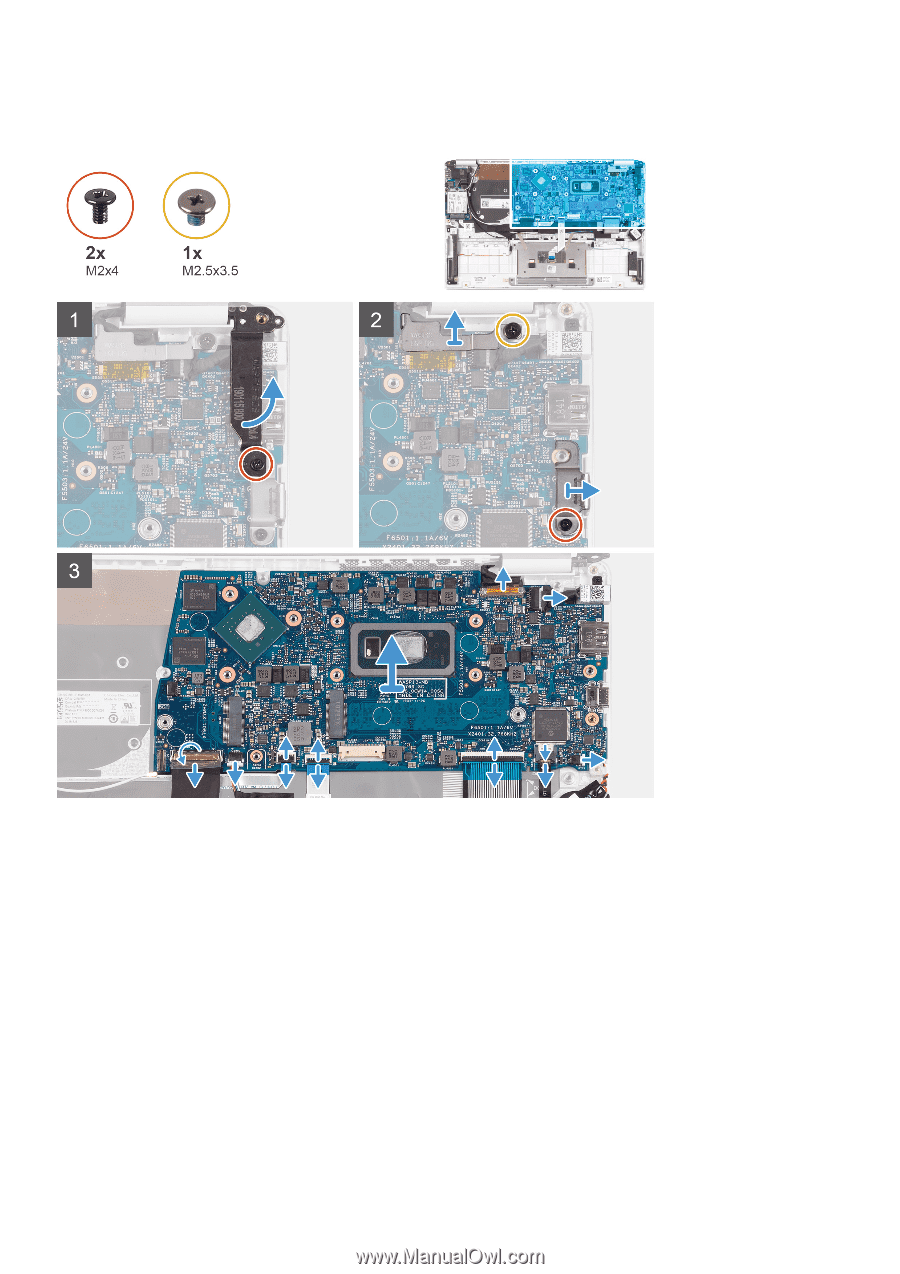
About this task The following image indicates the location of system board and provides a visual representation of the removal procedure. Steps 1. Remove the screw (M2x4) screw that secures the right display hinge to the system board. 2. Remove the screw (M2x4) that secures the display-cable bracket to the system board. 3. Remove the screw (M2.5x3.5) screw that secures the USB Type-C port bracket to the system board. 4. Peel the tape that secures the I/O-board cable to the system board. 5. Open the latch and disconnect the I/O-board cable from the system board. 6. Disconnect the speaker cable from the system board. 7. Open the latch and disconnect the fingerprint-reader cable from the system board. 8. Open the latch and disconnect the touchpad cable from the system board. 9. Open the latch and disconnect the keyboard cable from the system board. 10. Open the latch and disconnect the keyboard backlit cable from the system board. 11. Disconnect the coin-cell battery cable from the system board. 12. Disconnect the power-adapter port cable from the system board. 13. Using the pull tab, disconnect the display cable from the system board. 14. Gently release the ports on the system board from the slots on the palm-rest and keyboard assembly and lift the system board off the palm-rest and keyboard assembly. Removing and installing components 45
-
 1
1 -
2
-
3
-
4
-
5
-
6
-
7
-
8
-
9
-
10
-
11
-
12
-
13
-
14
-
15
-
16
-
17
-
18
-
19
-
20
-
21
-
22
-
23
-
24
-
25
-
26
-
27
-
28
-
29
-
30
-
31
-
32
-
33
-
34
-
35
-
36
-
37
-
38
-
39
-
 40
40 -
 41
41 -
 42
42 -
 43
43 -
 44
44 -
 45
45 -
 46
46 -
 47
47 -
 48
48 -
 49
49 -
 50
50 -
51
-
52
-
53
-
54
-
55
-
56
-
57
-
58
-
59
-
60
-
61
-
62
-
63
-
64
-
65
-
66
-
67
-
68
-
69
-
70
-
71
-
72
-
73
-
74
-
75
-
76
-
77
-
78
-
79
-
80
-
81
 |
 |