Dell Inspiron 5391 Service Manual
Dell Inspiron 5391 Manual
 |
View all Dell Inspiron 5391 manuals
Add to My Manuals
Save this manual to your list of manuals |
Dell Inspiron 5391 manual content summary:
- Dell Inspiron 5391 | Service Manual - Page 1
Inspiron 5391 Service Manual Regulatory Model: P114G Regulatory Type: P114G001 - Dell Inspiron 5391 | Service Manual - Page 2
and tells you how to avoid the problem. WARNING: A WARNING indicates a potential for property damage, personal injury, or death. © 2018 - 2019 Dell Inc. or its subsidiaries. All rights reserved. Dell, EMC, and other trademarks are trademarks of Dell Inc. or its subsidiaries. Other trademarks may - Dell Inspiron 5391 | Service Manual - Page 3
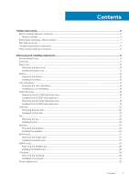
Contents 1 Safety instructions...6 Before working inside your computer...6 Before you begin ...6 Electrostatic discharge-ESD protection...7 ESD field service kit ...7 Transporting sensitive components...8 After working inside your computer...8 2 Removing and installing components 9 Recommended - Dell Inspiron 5391 | Service Manual - Page 4
Removing the power-adapter port...33 Installing the power-adapter port...33 Display assembly...34 Removing the display assembly...34 Installing the display assembly...37 I/O board...39 Removing the I/O board...39 Installing the I/O board...40 Power-button board...41 Removing the power-button board - Dell Inspiron 5391 | Service Manual - Page 5
...67 Clearing CMOS settings...75 Clearing BIOS (System Setup) and System passwords 75 5 Troubleshooting...76 Enhanced Pre-Boot System Assessment (ePSA) diagnostics 76 Running the ePSA diagnostics...76 power release...79 Wi-Fi power cycle...80 6 Getting help and contacting Dell 81 Contents 5 - Dell Inspiron 5391 | Service Manual - Page 6
, not by its pins. CAUTION: You should only perform troubleshooting and repairs as authorized or directed by the Dell technical assistance team. Damage due to servicing that is not authorized by Dell is not covered by your warranty. See the safety instructions that shipped with the product or at www - Dell Inspiron 5391 | Service Manual - Page 7
shut-down instructions. 3. Disconnect such as intermittent problems or a shortened Dell products, the sensitivity to static damage is now higher than in previous Dell damage to recognize and troubleshoot is the intermittent (also known as bonding. Use only Field Service kits with a wrist strap, mat, - Dell Inspiron 5391 | Service Manual - Page 8
for safe transport. ESD protection summary It is recommended that all field service technicians use the traditional wired ESD grounding wrist strap and protective anti-static mat at all times when servicing Dell products. In addition, it is critical that technicians keep sensitive parts separate - Dell Inspiron 5391 | Service Manual - Page 9
2 Removing and installing components Recommended tools The procedures in this document may require the following tools: • Phillips screwdriver #1 • Flat-head screwdriver • Plastic scribe Screw list NOTE: When removing screws from a component, it is recommended to note the screw type, the - Dell Inspiron 5391 | Service Manual - Page 10
Component Left display hinge Hinges Display-cable bracket Secured to Display back-cover and antenna assembly Display back-cover and antenna assembly System board Screw type M2.5x3.5 M2.5x2.5 M2.5x3.5 Quantity 2 6 1 Screw image Power-adapter port Palm-rest and keyboard M2x3 1 assembly Power - Dell Inspiron 5391 | Service Manual - Page 11
Steps 1. Loosen the three captive screws on the base cover. 2. Remove the four screws (M2x6) that secure the base cover to the palm-rest and keyboard assembly. 3. Pry the base cover starting from the top-left corner of the palm-rest and keyboard assembly. 4. Lift the base cover off the palm-rest and - Dell Inspiron 5391 | Service Manual - Page 12
Steps 1. Place the computer with the hinges facing towards you. 2. Align the base cover on the palm-rest and keyboard assembly, and snap the base cover into place. 3. Replace the four screws (M2x6) that secure the base cover to the palm-rest and keyboard assembly. 4. Tighten the three captive screws - Dell Inspiron 5391 | Service Manual - Page 13
Steps 1. Disconnect the battery cable from the system board. 2. Remove the four screws (M2x2) that secure the battery to the palm-rest and keyboard assembly. 3. Remove the screw (M1.6x4) that secures the battery to the system board and palm-rest and keyboard assembly. 4. Lift the battery off the - Dell Inspiron 5391 | Service Manual - Page 14
Steps 1. Connect the battery cable to the system board. 2. Replace the four screws (M2x2) that secure the battery to the palm-rest and keyboard assembly. 3. Replace the screw (M1.6x4) that secures the battery to the system board and palm-rest and keyboard assembly. Next steps 1. Install the base - Dell Inspiron 5391 | Service Manual - Page 15
Steps 1. Disconnect the coin-cell battery cable from the system board. 2. Remove the coin-cell battery cable from the routing guide. 3. Peel the coin-cell battery off the palm-rest and keyboard assembly. Installing the coin-cell battery Prerequisites If you are replacing a component, remove the - Dell Inspiron 5391 | Service Manual - Page 16
Adhere the coin-cell battery to the slot on the palm-rest and keyboard assembly. 2. Route the coin-cell battery cable through the routing guide. 3. Connect the coin-cell battery cable to the system board. Next steps 1. Install the battery. 2. Install the base cover. 3. Follow the procedure in After - Dell Inspiron 5391 | Service Manual - Page 17
Steps 1. Remove the screw (M2x2.5) that secures the solid-state drive to the system board. 2. Slide and remove the solid-state drive from the solid-state drive slot on the system board. Installing the M.2 2280 solid-state drive Prerequisites If you are replacing a component, remove the existing - Dell Inspiron 5391 | Service Manual - Page 18
Steps 1. Align the notch on the solid-state drive with the tab on the solid-state drive slot and slide the solid-state drive into the solid-state drive slot on the system board. 2. Replace the screw (M2x2.5) that secures the solid-state drive to the system board. Next steps 1. Install the battery. - Dell Inspiron 5391 | Service Manual - Page 19
Steps 1. Remove the screw (M2x2.5) that secures the solid-state drive bracket to the system board. 2. Slide and remove the solid-state drive bracket off the solid-state drive on the system board. 3. Slide and remove the solid-state drive off the solid-state drive slot on the system board. Installing - Dell Inspiron 5391 | Service Manual - Page 20
Steps 1. Align the notch on the solid-state drive with the tab on the solid-state drive slot and slide the solid-state drive into the solid-state drive slot on the system board. 2. Slide the solid-state bracket on to the solid-state drive on the system board. 3. Replace the screw (M2x2.5) that - Dell Inspiron 5391 | Service Manual - Page 21
Steps 1. Peel the mylar tape that secures the heat sink to the system board. 2. In the reverse sequential order (7>6>5>4>3>2>1), loosen the seven captive screws that secure the heat sink to the system board. 3. Lift the heat sink off the system board. Installing the heat sink Prerequisites If you - Dell Inspiron 5391 | Service Manual - Page 22
Steps 1. Align and place the screw holes on the heat sink with the screw holes on the system board. 2. In sequential order (as indicated on the heat sink), tighten the seven captive screws that secure the heat sink to the system board. 3. Adhere the mylar tape that secures the heat sink to the - Dell Inspiron 5391 | Service Manual - Page 23
Steps 1. Disconnect the I/O-board cable from the system board and I/O board. NOTE: This step is only applicable for computers shipped with a WWAN configuration. 2. Remove the two (M2x3) screws that secure the fan to the system board. 3. Lift the fan slightly off the palm-rest and keyboard assembly. - Dell Inspiron 5391 | Service Manual - Page 24
Steps 1. Connect the fan cable to the system board. 2. Align the screw holes on the fan with the screw holes on the palm-rest and keyboard assembly. 3. Replace the two (M2x3) screws that secure the fan to the palm-rest and keyboard assembly. 4. Connect the I/O-board cable to the system board and I/O - Dell Inspiron 5391 | Service Manual - Page 25
the speaker cable to the palm-rest and keyboard assembly. 4. Note the routing of the speaker cable and remove the speaker cable from the routing guides on the palm-rest and keyboard assembly. Removing and installing components 25 - Dell Inspiron 5391 | Service Manual - Page 26
posts and rubber grommets, place the speakers in the slots on the palm-rest and keyboard assembly. 2. Route the speaker cable through the routing guides on the palm-rest and keyboard assembly. 3. Adhere the tapes that secure the speaker cable to the palm-rest and keyboard assembly. 4. Connect the - Dell Inspiron 5391 | Service Manual - Page 27
Next steps 1. Install the battery. 2. Install the base cover. 3. Follow the procedure in After working inside your computer. WLAN card Removing the WLAN card Prerequisites 1. Follow the procedure in Before working inside your computer. 2. Remove the base cover. 3. Remove the battery. About this task - Dell Inspiron 5391 | Service Manual - Page 28
About this task The following image indicates the location of WLAN card and provides a visual representation of the installation procedure. Steps 1. Connect the antenna cables to the WLAN card. 2. Align the notch on the WLAN card with the tab on the WLAN card slot and insert the WLAN card at an - Dell Inspiron 5391 | Service Manual - Page 29
Steps 1. Remove the screw (M2x2.5) that secures the WWAN card bracket to the WWAN card. 2. Note the alignment of the WWAN-card bracket before lifting it off the WWAN card. 3. Disconnect the antenna cables from the WWAN card. 4. Slide and remove the WWAN card from the WWAN card slot. Installing the - Dell Inspiron 5391 | Service Manual - Page 30
Steps 1. Align the notch on the WWAN card with the tab on the WWAN-card slot and insert the WWAN card at an angle into the WWAN-card slot. 2. Connect the antenna cables to the WWAN card and align the WWAN-card bracket on the WWAN card. 3. Replace the screw (M2x2.5) that secures the WWAN bracket to - Dell Inspiron 5391 | Service Manual - Page 31
Steps 1. Peel the tapes that secure the touchpad to the palm-rest and keyboard assembly. 2. Open the latch and disconnect the touchpad cable from the system board. 3. Remove the three (M1.6x2) screws that secure the touchpad bracket to the palm-rest and keyboard assembly. 4. Lift the touchpad - Dell Inspiron 5391 | Service Manual - Page 32
Steps 1. Align and place the touchpad into the slot on the palm-rest and keyboard assembly. 2. Replace the two (M1.6x2) screws that secure the touchpad to the palm-rest and keyboard assembly. 3. Align and place the touchpad bracket into the slot on the palm-rest and keyboard assembly. 4. Replace the - Dell Inspiron 5391 | Service Manual - Page 33
Power-adapter port Removing the power-adapter port Prerequisites 1. Follow the procedure in Before working inside your computer. 2. Remove the base cover. 3. Remove the battery. About this task The following image indicates the location of power-adapter port and provides a visual representation of - Dell Inspiron 5391 | Service Manual - Page 34
Steps 1. Connect the power-adapter port cable to the system board. 2. Replace the screw (M2x3) that secures the power-adapter port to the palm-rest and keyboard assembly. 3. Align and place the display-cable bracket on the system board. 4. Replace the screw (M2.5x3.5) that secure the display-cable - Dell Inspiron 5391 | Service Manual - Page 35
Removing and installing components 35 - Dell Inspiron 5391 | Service Manual - Page 36
Steps 1. Remove the screw (M2.5x3.5) that secures the display-cable bracket to the system board. 2. Lift the display-cable bracket off the system board. 3. Using the pull tab, disconnect the display cable from the system board. 4. Remove the two screws (M2.5x3.5) that secure the left display hinge - Dell Inspiron 5391 | Service Manual - Page 37
Installing the display assembly Prerequisites If you are replacing a component, remove the existing component before performing the installation procedure. About this task The following image indicates the location of display assembly and provides a visual representation of the installation - Dell Inspiron 5391 | Service Manual - Page 38
Steps 1. Align and place the palm-rest and keyboard assembly on the display assembly. 2. Using the alignment posts, close the display hinges. 3. Replace the two screws (M2.5x3.5) that secures the left display hinge to the I/O board and palm-rest and keyboard assembly. 4. Replace the screw (M2x4) - Dell Inspiron 5391 | Service Manual - Page 39
I/O board Removing the I/O board Prerequisites 1. Follow the procedure in Before working inside your computer. 2. Remove the base cover. 3. Remove the battery. 4. Remove the fan. About this task The following image indicates the location of I/O board and provides a visual representation of the - Dell Inspiron 5391 | Service Manual - Page 40
4. Open the latch and disconnect the I/O-board cable from the I/O board. 5. Remove the screw (M2.5x2.5) that secures the I/O board to the palm-rest and keyboard assembly. 6. Remove the screw (M2x3) that secures the I/O board to the palm-rest and keyboard assembly. 7. Lift the I/O board off the palm- - Dell Inspiron 5391 | Service Manual - Page 41
5. Adhere the tape that secures the I/O board to the I/O board. 6. Using the alignment posts, close the display hinges. 7. Replace the two screws (M2.5x3.5) that secure the left display hinge to the I/O board and palm-rest and keyboard assembly. Next steps 1. Install the fan. 2. Install the battery. - Dell Inspiron 5391 | Service Manual - Page 42
Installing the power-button board Prerequisites If you are replacing a component, remove the existing component before performing the installation procedure. About this task The following image indicates the location of power-button board and provides a visual representation of the installation - Dell Inspiron 5391 | Service Manual - Page 43
1. Follow the procedure in Before working inside your computer. 2. Remove the base cover. 3. Remove the battery. 4. Remove the WLAN card. 5. Remove the fan. 6. Remove the I/O board. About this task The following image indicates the location of power button with fingerprint reader and provides a - Dell Inspiron 5391 | Service Manual - Page 44
Steps 1. Align and place the power button with fingerprint reader on the palm-rest and keyboard assembly. 2. Replace the screw (M1.6x2) that secure the power button with fingerprint reader to the palm-rest and keyboard assembly. 3. Connect the fingerprint-reader cable to the fingerprint-reader board - Dell Inspiron 5391 | Service Manual - Page 45
About this task The following image indicates the location of system board and provides a visual representation of the removal procedure. Steps 1. Remove the screw (M2x4) screw that secures the right display hinge to the system board. 2. Remove the screw (M2x4) that secures the display-cable - Dell Inspiron 5391 | Service Manual - Page 46
Installing the system board Prerequisites If you are replacing a component, remove the existing component before performing the installation procedure. About this task The following image indicates the location of system board and provides a visual representation of the installation procedure. Steps - Dell Inspiron 5391 | Service Manual - Page 47
9. Connect the fingerprint-reader cable to the system board and close the latch to secure the cable. 10. Connect the speaker cable to the system board. 11. Connect the I/O-board cable to the system board and close the latch to secure the cable. 12. Adhere the tape that secures the I/O-board cable to - Dell Inspiron 5391 | Service Manual - Page 48
Steps 1. Carefully pry the edges of the display bezel off the display back-cover and antenna assembly. 2. Remove the display bezel off the display back-cover and antenna assembly. Installing the display bezel Prerequisites NOTE: This procedure is not applicable to computers shipped with a WWAN - Dell Inspiron 5391 | Service Manual - Page 49
Steps Align the display bezel with the display back-cover and antenna assembly, and gently snap the display bezel into place. Next steps 1. Install the display assembly. 2. Install the WLAN card. 3. Install the battery. 4. Install the base cover. 5. Follow the procedure in After working inside your - Dell Inspiron 5391 | Service Manual - Page 50
50 Removing and installing components - Dell Inspiron 5391 | Service Manual - Page 51
Removing and installing components 51 - Dell Inspiron 5391 | Service Manual - Page 52
Steps 1. Using a plastic scribe, slide out the pull tab of the SR tape from both sides of the display panel. 2. Pull out a small section of the SR tape. 3. Roll the SR tape around the plastic scribe. NOTE: To avoid severing/breaking the SR tape, pull out only a small section of the SR tape and then - Dell Inspiron 5391 | Service Manual - Page 53
Removing and installing components 53 - Dell Inspiron 5391 | Service Manual - Page 54
Steps 1. Peel off the transparent protective films from the SR tapes. 2. Align and adhere both the SR tapes to the plastic edge of the display back-cover. 3. Peel off the blue protective films from the SR tapes. 4. Starting from the top, align and place the display panel on the display back-cover. - Dell Inspiron 5391 | Service Manual - Page 55
Display hinges Removing the display hinges Prerequisites NOTE: This procedure is not applicable to computers shipped with a WWAN configuration. 1. Follow the procedure in Before working inside your computer. 2. Remove the base cover. 3. Remove the battery. 4. Remove the WLAN card. 5. Remove the - Dell Inspiron 5391 | Service Manual - Page 56
About this task The following image indicates the location of display hinges and provides a visual representation of the installation procedure. Steps 1. Align the screw holes on the hinges with the screw holes on the display back-cover. 2. Replace the two (M2x2) screws that secure the display - Dell Inspiron 5391 | Service Manual - Page 57
About this task The following image indicates the location of camera and provides a visual representation of the removal procedure. Steps 1. Peel the tape that secures the camera to the display back-cover 2. Using a plastic scribe, pry the camera from the alignment post on the display back-cover. - Dell Inspiron 5391 | Service Manual - Page 58
Steps 1. Adhere the camera to the display cable (tape) and connect the camera cable to the camera and turn it over. 2. Using the alignment post, turn the camera over and adhere to the display back-cover. 3. Adhere the tape that secures the camera to the display back-cover. Next steps 1. Install the - Dell Inspiron 5391 | Service Manual - Page 59
10. Remove the camera. About this task The following image indicates the display back-cover and provides a visual representation of the removal procedure. Steps After performing all the prerequisites, we are left with the display back-cover. NOTE: Antenna cables are a part of the palm-rest and - Dell Inspiron 5391 | Service Manual - Page 60
Steps Place the display back-cover on a flat surface. NOTE: Antenna cables are a part of the palm-rest and keyboard assembly for computers shipping with WLAN configurations. Next steps 1. Install the camera. 2. Install the display cable. 3. Install the display panel. 4. Install the display hinges. - Dell Inspiron 5391 | Service Manual - Page 61
Steps 1. Peel off the tape securing the display cable to the back-cover. 2. Peel the display cable off the display back-cover. Installing the display cable Prerequisites NOTE: This procedure is not applicable to computers shipped with a WWAN configuration. If you are replacing a component, remove - Dell Inspiron 5391 | Service Manual - Page 62
Steps 1. Adhere the tape securing the display cable to the back-cover. 2. Adhere the display cable to the display back-cover. Next steps 1. Install the display bezel. 2. Install the display panel. 3. Install the display assembly. 4. Install the battery. 5. Install the base cover. 6. Follow the - Dell Inspiron 5391 | Service Manual - Page 63
About this task The following image indicates the palm-rest and keyboard assembly and provides a visual representation of the removal procedure. Steps After performing the steps in the pre-requisites, we are left with the palm-rest and keyboard assembly. NOTE: Antenna cables are a part of the - Dell Inspiron 5391 | Service Manual - Page 64
Steps Place the palm-rest and keyboard assembly on a flat surface. NOTE: Antenna cables are a part of the display back-cover for computers shipping with WWAN configuration. Next steps 1. Install the touchpad. 2. Install the power-adapter port. 3. Install the power button with fingerprint reader or - Dell Inspiron 5391 | Service Manual - Page 65
Intel Serial IO driver In the Device Manager, check if the Intel Serial IO driver is installed. Install the driver updates from www.dell.com/support. Intel Trusted Execution Engine Interface In the Device Manager, check if the Intel Trusted Execution Engine Interface driver is installed. Install the - Dell Inspiron 5391 | Service Manual - Page 66
information about the hardware installed in your computer, such as the amount of RAM and the size of the hard drive. • Change the system configuration information 1. Turn on (or restart) your computer. 2. During POST, when the DELL logo is displayed, watch for the F2 prompt to appear, and then press - Dell Inspiron 5391 | Service Manual - Page 67
optical drive or hard drive). During the Power-on Self Test (POST), when the Dell logo appears, you can: • Access System Setup by pressing F2 key • Bring up . Displays the ownership date of the computer. Displays the express service code of the computer. Displays the ownership tag of the computer - Dell Inspiron 5391 | Service Manual - Page 68
Overview Processor Type Displays the processor type. Maximum Clock Speed Displays the maximum processor clock speed. Core Count Displays the number of cores on the processor. Processor L2 Cache Displays the processor L2 Cache size. Processor ID Displays the processor identification code. - Dell Inspiron 5391 | Service Manual - Page 69
Enables or disables microphone. Default: ON. Enable Internal Speaker Enables or disables internal speaker. Default: ON. USB Configuration Enable Boot Support Enable External USB Ports SATA Operation Enables or disables booting from USB mass storage devices such as external hard drive, optical - Dell Inspiron 5391 | Service Manual - Page 70
Enables or disables BIOS updates through UEFI capsule update packages. Enable or disable the BIOS module interface of the optional Computrace(R) Service from Absolute Software. Enables or disables Platform Trust Technology (PTT) visibility to the operating system. Default: ON. PPI Bypass for Clear - Dell Inspiron 5391 | Service Manual - Page 71
" password). System Password Sets, Changes, or deletes the system password. Enable Master Password Lockout Enables or disables the master password support. Default: OFF. Table 7. System setup options-Secure Boot menu Secure Boot Enable Secure Boot Enables or disables the computer to boos - Dell Inspiron 5391 | Service Manual - Page 72
Rapid Start will be disabled automatically, and the operating system power option will be blank if it was set to Sleep. Enable USB Wake Support Enables the USB devices to wake the computer from Standby mode. Default: OFF. Enable Intel Speed Shift Technology Enables or disables Intel Speed Shift - Dell Inspiron 5391 | Service Manual - Page 73
Table 11. System setup options-Wireless menu Wireless Wireless Switch Determines which wireless devices can be controlled by the Wireless Switch. For Windows 8 systems, this is controlled by an operating system drive directly. As a result, the setting does not affect the Wireless Switch behavior. - Dell Inspiron 5391 | Service Manual - Page 74
system. Once set in BIOS, the Asset Tag cannot be changed. Service Tag Displays the Service Tag of the computer. BIOS Recovery from Hard Drive Enables the computer 16. System setup options-SupportAssist menu SupportAssist Dell Auto operating system Recovery Threshold Controls the automatic - Dell Inspiron 5391 | Service Manual - Page 75
. Clearing BIOS (System Setup) and System passwords About this task To clear the system or BIOS passwords, contact Dell technical support as described at www.dell.com/contactdell. NOTE: For information on how to reset Windows or application passwords, refer to the documentation accompanying Windows - Dell Inspiron 5391 | Service Manual - Page 76
Troubleshooting successfully • View error messages that inform you of problems encountered during testing NOTE: Some tests for specific devices are displayed. Note the error code and validation number and contact Dell. System diagnostic lights Battery-status light Indicates the power and battery- - Dell Inspiron 5391 | Service Manual - Page 77
RAM is detected. The following table shows different power and battery-status light patterns and associated problems. Table 17. LED codes Diagnostic light codes Problem of fault Repair instruction M-BIST ( problem with the system Indicates a problem with the system board. board. Troubleshooting - Dell Inspiron 5391 | Service Manual - Page 78
-board failures. NOTE: M-BIST can be manually-initiated before POST (Power-On Self-Test). determine if a screen abnormality is an inherent problem with the LCD screen of the computer, with Dell computers installed with Windows 10 operating system. It consists of tools to diagnose and troubleshoot - Dell Inspiron 5391 | Service Manual - Page 79
from the Dell Support website to troubleshoot and fix your computer when it fails to boot into their primary operating system due to software or hardware failures. For more information about the Dell SupportAssist OS Recovery, see Dell SupportAssist OS Recovery User's Guide at www.dell.com/ support - Dell Inspiron 5391 | Service Manual - Page 80
Wi-Fi connectivity issues a Wi-Fi power cycle procedure may be performed. The following procedure provides the instructions on how to conduct a Wi-Fi power cycle: NOTE: Some ISPs (Internet Service Providers) provide a modem/router combo device. Steps 1. Turn off your computer. 2. Turn off the modem - Dell Inspiron 5391 | Service Manual - Page 81
Self-help resources Resource location Information about Dell products and services www.dell.com My Dell Tips Contact Support Online help for operating system Troubleshooting information, user manuals, setup instructions, product specifications, technical help blogs, drivers, software
-
 1
1 -
 2
2 -
 3
3 -
 4
4 -
 5
5 -
 6
6 -
 7
7 -
8
-
9
-
10
-
11
-
12
-
13
-
14
-
15
-
16
-
17
-
18
-
19
-
20
-
21
-
22
-
23
-
24
-
25
-
26
-
27
-
28
-
29
-
30
-
31
-
32
-
33
-
34
-
35
-
36
-
37
-
38
-
39
-
40
-
41
-
42
-
43
-
44
-
45
-
46
-
47
-
48
-
49
-
50
-
51
-
52
-
53
-
54
-
55
-
56
-
57
-
58
-
59
-
60
-
61
-
62
-
63
-
64
-
65
-
66
-
67
-
68
-
69
-
70
-
71
-
72
-
73
-
74
-
75
-
76
-
77
-
78
-
79
-
80
-
81
 |
 |

Inspiron 5391
Service Manual
Regulatory Model: P114G
Regulatory Type: P114G001