2012 Yamaha Motorsports RS Venture Owners Manual - Page 71
2012 Yamaha Motorsports RS Venture Manual

Page 71 highlights
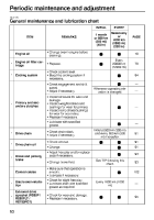
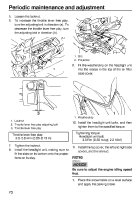
Periodic maintenance and adjustment 3. Remove the screws, and then remove the cable guide. To install the top cover 1. Connect the main switch coupler. 2. Place the top cover in the original position, making sure to fit the projections on the cover into the slots in the headlight unit. 2 1 1 1. Screw 2. Cable guide 4. Loosen the quick fastener screws. 1. Top cover 3. 4. Tighten the quick fastener screws. Pass the brake hose, throttle cable, parking brake cable and wire harness through the cable guide, place the cable guide in the original position, and then install the screws. 1. Quick fastener screw 2. Top cover 1 5. Lift up the rear of the top cover, disconnect the main switch coupler, and then remove the cover. 1 1. Cable guide 5. 6. Connect the auxiliary DC jack coupler. Install the left side cover and the shroud. ECS00372 NOTICE 2 1. Top cover 2. Main switch coupler G Make sure that all cables, hoses and leads are routed properly before installing the shroud and covers. 65
-
 1
1 -
2
-
3
-
4
-
5
-
6
-
7
-
8
-
9
-
10
-
11
-
12
-
13
-
14
-
15
-
16
-
17
-
18
-
19
-
20
-
21
-
22
-
23
-
24
-
25
-
26
-
27
-
28
-
29
-
30
-
31
-
32
-
33
-
34
-
35
-
36
-
37
-
38
-
39
-
40
-
41
-
42
-
43
-
44
-
45
-
46
-
47
-
48
-
49
-
50
-
51
-
52
-
53
-
54
-
55
-
56
-
57
-
58
-
59
-
60
-
61
-
62
-
63
-
64
-
65
-
 66
66 -
 67
67 -
 68
68 -
 69
69 -
 70
70 -
 71
71 -
 72
72 -
 73
73 -
 74
74 -
 75
75 -
 76
76 -
77
-
78
-
79
-
80
-
81
-
82
-
83
-
84
-
85
-
86
-
87
-
88
-
89
-
90
-
91
-
92
-
93
-
94
-
95
-
96
-
97
-
98
-
99
-
100
-
101
-
102
-
103
-
104
-
105
-
106
-
107
-
108
-
109
-
110
-
111
-
112
-
113
-
114
-
115
-
116
-
117
-
118
-
119
-
120
-
121
-
122
-
123
-
124
-
125
-
126
-
127
-
128
-
129
-
130
-
131
-
132
-
133
-
134
-
135
-
136
-
137
-
138
-
139
-
140
-
141
-
142
 |
 |
