2012 Yamaha Motorsports RS Venture Owners Manual - Page 118
2012 Yamaha Motorsports RS Venture Manual

Page 118 highlights
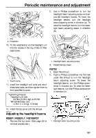
Periodic maintenance and adjustment RST90PGT 1 2 7 3 4 5 6 7 1. 2. 3. 4. 5. 6. 7. Fuse box "IGN" (ignition) fuse "S/H" (helmet shield heater jack) fuse "HEAD" (headlight) fuse "SIG" (signaling system) fuse "DC" (auxiliary DC jack) fuse Spare fuse Specified fuses: Main fuse: 40.0 A EPS fuse: 40.0 A Fuel injection system fuse: 10.0 A Ignition fuse: 15.0 A Radiator fan fuse: RS90P 5.0 A RS90PLT 5.0 A Headlight fuse: 20.0 A Signaling system fuse: RS90P 3.0 A RS90PLT 3.0 A RST90PGT 7.5 A Auxiliary DC jack fuse: 3.0 A Helmet shield heater jack fuse: 3.0 A Spare fuses: RS90P / RS90PLT 20.0 A, 15.0 A, 10.0 A, 5.0 A, 3.0 A RST90PGT 20.0 A, 15.0 A, 10.0 A, 7.5 A, 3.0 A 11. Connect the negative battery lead by installing the bolt. 12. Install the battery cover, and then hook the battery band onto the holder. 13. Install the air filter case by reversing the removal steps 4-7. 14. Install the headlight unit, making sure to fit the slots on its bottom onto the projections on its stay. 112
-
 1
1 -
2
-
3
-
4
-
5
-
6
-
7
-
8
-
9
-
10
-
11
-
12
-
13
-
14
-
15
-
16
-
17
-
18
-
19
-
20
-
21
-
22
-
23
-
24
-
25
-
26
-
27
-
28
-
29
-
30
-
31
-
32
-
33
-
34
-
35
-
36
-
37
-
38
-
39
-
40
-
41
-
42
-
43
-
44
-
45
-
46
-
47
-
48
-
49
-
50
-
51
-
52
-
53
-
54
-
55
-
56
-
57
-
58
-
59
-
60
-
61
-
62
-
63
-
64
-
65
-
66
-
67
-
68
-
69
-
70
-
71
-
72
-
73
-
74
-
75
-
76
-
77
-
78
-
79
-
80
-
81
-
82
-
83
-
84
-
85
-
86
-
87
-
88
-
89
-
90
-
91
-
92
-
93
-
94
-
95
-
96
-
97
-
98
-
99
-
100
-
101
-
102
-
103
-
104
-
105
-
106
-
107
-
108
-
109
-
110
-
111
-
112
-
 113
113 -
 114
114 -
 115
115 -
 116
116 -
 117
117 -
 118
118 -
 119
119 -
 120
120 -
 121
121 -
 122
122 -
 123
123 -
124
-
125
-
126
-
127
-
128
-
129
-
130
-
131
-
132
-
133
-
134
-
135
-
136
-
137
-
138
-
139
-
140
-
141
-
142
 |
 |
