2011 Yamaha Motorsports RS Vector GT Owners Manual - Page 70
2011 Yamaha Motorsports RS Vector GT Manual

Page 70 highlights
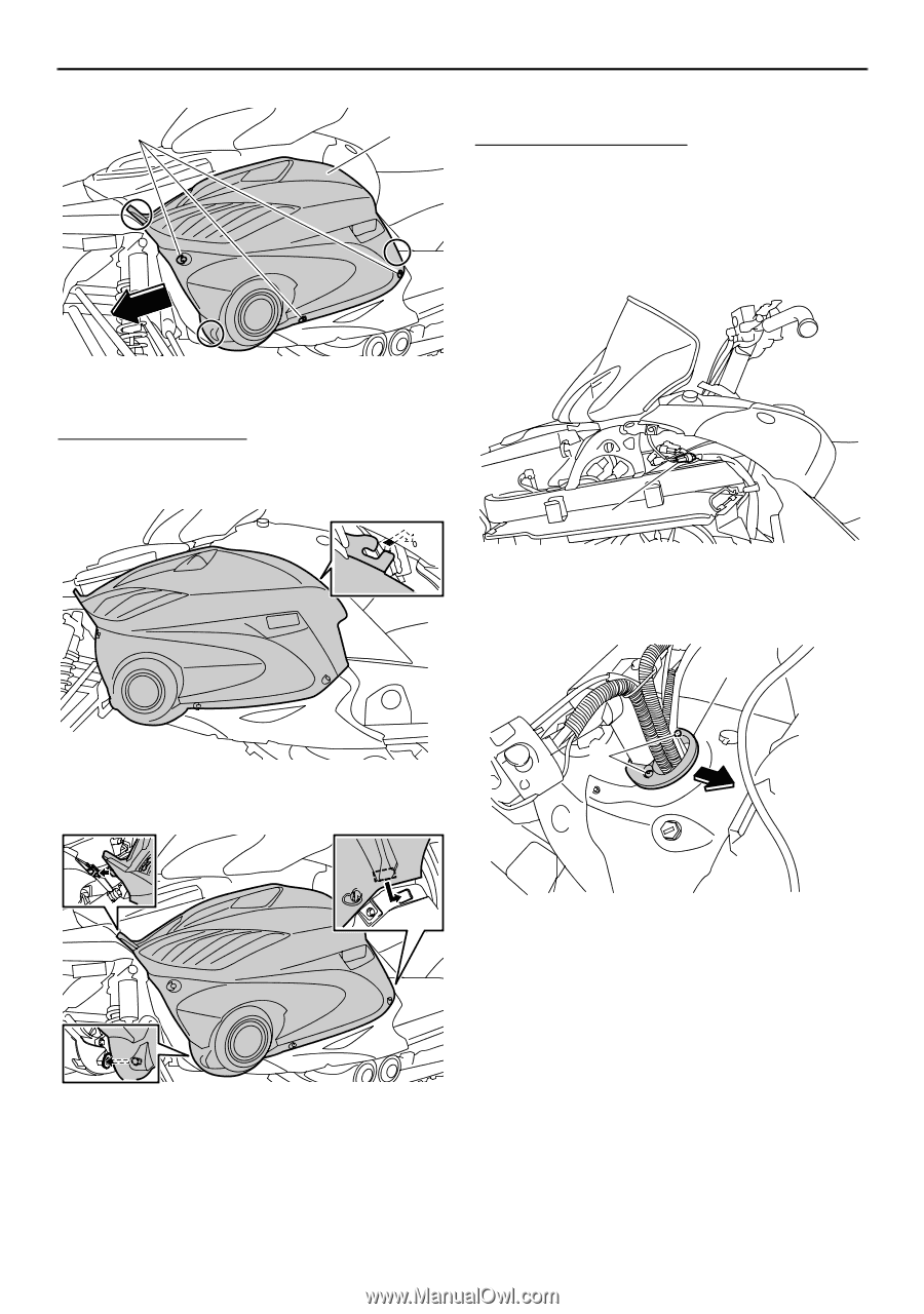
Periodic maintenance and adjustment 1 2 Top cover (RS90GT / RS90LTGT) To remove the top cover 1. Remove the shroud and the left side cover. (See the above procedures.) 2. Remove the plastic band that is holding the auxiliary DC lead, and then disconnect the auxiliary DC jack coupler. 1. Fastener 2. Left side cover To install a side cover 1. Fit the projection on the rear of the side cover into the hole in the fuel tank cover. 1 1. Auxiliary DC jack coupler 3. Remove the screws, and then remove the cable guide. 2 1 2. Fit the projections on the side cover into the slots as shown. 1. Screw 2. Cable guide 4. Loosen the quick fastener screws. 3. 4. Tighten the fasteners. Install the shroud. 64
-
 1
1 -
2
-
3
-
4
-
5
-
6
-
7
-
8
-
9
-
10
-
11
-
12
-
13
-
14
-
15
-
16
-
17
-
18
-
19
-
20
-
21
-
22
-
23
-
24
-
25
-
26
-
27
-
28
-
29
-
30
-
31
-
32
-
33
-
34
-
35
-
36
-
37
-
38
-
39
-
40
-
41
-
42
-
43
-
44
-
45
-
46
-
47
-
48
-
49
-
50
-
51
-
52
-
53
-
54
-
55
-
56
-
57
-
58
-
59
-
60
-
61
-
62
-
63
-
64
-
 65
65 -
 66
66 -
 67
67 -
 68
68 -
 69
69 -
 70
70 -
 71
71 -
 72
72 -
 73
73 -
 74
74 -
 75
75 -
76
-
77
-
78
-
79
-
80
-
81
-
82
-
83
-
84
-
85
-
86
-
87
-
88
-
89
-
90
-
91
-
92
-
93
-
94
-
95
-
96
-
97
-
98
-
99
-
100
-
101
-
102
-
103
-
104
-
105
-
106
-
107
-
108
-
109
-
110
-
111
-
112
-
113
-
114
-
115
-
116
-
117
-
118
-
119
-
120
-
121
-
122
-
123
-
124
-
125
-
126
-
127
-
128
-
129
-
130
-
131
-
132
-
133
-
134
-
135
-
136
-
137
-
138
-
139
-
140
 |
 |
Periodic maintenance and adjustment
64
To install a side cover
1.
Fit the projection on the rear of the side
cover into the hole in the fuel tank cover.
2.
Fit the projections on the side cover into
the slots as shown.
3.
Tighten the fasteners.
4.
Install the shroud.
Top cover (RS90GT / RS90LTGT)
To remove the top cover
1.
Remove the shroud and the left side cov-
er. (See the above procedures.)
2.
Remove the plastic band that is holding
the auxiliary DC lead, and then discon-
nect the auxiliary DC jack coupler.
3.
Remove the screws, and then remove
the cable guide.
4.
Loosen the quick fastener screws.
1. Fastener
2.
Left side cover
1
2
1.
Auxiliary DC jack coupler
1. Screw
2.
Cable guide
1
1
2