TASCAM Model 24 Owners Manual - Page 37
SIG indicators and level meters, Recording, Track level meters 1-12
 |
View all TASCAM Model 24 manuals
Add to My Manuals
Save this manual to your list of manuals |
Page 37 highlights
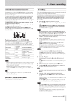
5 - Basic recording SIG indicators and level meters The channel 1-12, 13/14-19/20 SIG indicators and level meters shown on the Meter Screen can be used to check the levels of this unit's audio signals. The level meters are for visually checking signal levels and can also be used to check whether or not signals are being input to this unit. For example, even if nothing can be heard when monitoring, if the Meter Screen level meters are moving, signals are being input to this unit. The SIG indicators light green when signals (of at least −56 dB) are input through their channels. If a SIG indicator lights red, the input source signal is too loud or the GAIN knob is turned up too far. If the SIG indicator lights red even when the GAIN knob is turned all the way to the left, the input source signal is to loud. Lower its volume. Track level meters (1-12, 13/14-21/22) These show track playback signal or track input signal levels. Channels for which the MODE switch is set to "MTR" will show the following signal levels according to the operation status. REC button Unlit Transport status PLAY Blinking PLAY (recording standby) Stop Blinking (recording) Record Level meter display Track playback signal Playback signal Track input + playback signal Track input signal Track input signal NOTE When the playback signal is shown, the level of the recorded signal on the track is being shown, so the levels of the level meters cannot be changed. When the input signal is shown, adjusting channel 1-12, 13/14-19/20 GAIN knobs will change the levels of the level meters. TIP Please see "Meter Screen details" on page 26 for details about the Meter Screen. MAIN MIX L/R level meters (MAIN) These show the MAIN MIX L/R bus levels. Recording This unit can simultaneously record up to 24 tracks, including 22 channel inputs and the MAIN MIX L/R bus. The following recording operations assume that mics, guitars and other things to record have been connected to the unit, input signals have been assigned as track recording sources, monitoring equipment has been connected and a song has been loaded. 1. Press the REC buttons for channel to record. Press the REC button to start recording standby. It will blink red. When a MODE switch is set to "MTR", the signal from the input jack on that channel will be recorded. (See "Setting the MODE switch" on page 36) NOTE iiThe MAIN MIX L/R bus does not have a REC button, but it is always in recording standby. The signals of the MAIN MIX L/R bus will always be recorded if the 0 button is pressed. iiWhen the REC buttons of tracks that already have recordings is blinking, press them to make them unlit. 2. Set the recording levels. Use the GAIN knobs of each channel to adjust their input levels. Watch the SIG indicators above and to the right of the GAIN knobs, and set the levels suitably. At the same time, check that the sound heard through headphones or a monitoring system is not distorted and that an unintended effect has not been set. NOTE If an input is too loud, the SIG indicator will light red. If the SIG indicator lights red even when its GAIN knob is turned all the way to the left, lower the volume of the input source. 3. Press the 0 button. Recording will start and the 0 and 7/9 buttons will light. The REC buttons for tracks to record will stop blinking and stay lit. 4. When recording has completed, press the 8 button. 5. Use the m/, buttons and 8 button, for example to locate to a position you want to check. TIP For details about the locate function, see"Locate function" on page 40. 6. Press the 7/9 button to play the recorded tracks. Use the channel and MAIN faders to adjust the playback levels. Use the volume of the monitoring system to adjust the final monitoring level. Use the PAN knobs of each channel to set the position of each track signal between left and right speakers. NOTE iiThe channel PAN knobs and channel faders control the play- back output signals of already recorded tracks or the monitoring volume of input signals. They do not control signals to be recorded. iiIf you are not satisfied with a recording, repeat the above procedure from the beginning. TASCAM Model 24 37
-
 1
1 -
2
-
3
-
4
-
5
-
6
-
7
-
8
-
9
-
10
-
11
-
12
-
13
-
14
-
15
-
16
-
17
-
18
-
19
-
20
-
21
-
22
-
23
-
24
-
25
-
26
-
27
-
28
-
29
-
30
-
31
-
 32
32 -
 33
33 -
 34
34 -
 35
35 -
 36
36 -
 37
37 -
 38
38 -
 39
39 -
 40
40 -
 41
41 -
 42
42 -
43
-
44
-
45
-
46
-
47
-
48
-
49
-
50
-
51
-
52
-
53
-
54
-
55
-
56
-
57
-
58
-
59
-
60
-
61
-
62
-
63
-
64
-
65
-
66
-
67
-
68
-
69
-
70
-
71
-
72
-
73
-
74
-
75
-
76
-
77
-
78
-
79
-
80
-
81
-
82
-
83
-
84
-
85
-
86
-
87
-
88
-
89
-
90
-
91
-
92
-
93
-
94
-
95
-
96
-
97
-
98
-
99
-
100
-
101
-
102
-
103
-
104
-
105
-
106
-
107
-
108
-
109
-
110
-
111
-
112
-
113
-
114
-
115
-
116
-
117
-
118
-
119
-
120
-
121
-
122
-
123
-
124
-
125
-
126
-
127
-
128
-
129
-
130
-
131
-
132
-
133
-
134
-
135
-
136
-
137
-
138
-
139
-
140
-
141
-
142
-
143
-
144
-
145
-
146
-
147
-
148
-
149
-
150
-
151
-
152
-
153
-
154
-
155
-
156
-
157
-
158
-
159
-
160
-
161
-
162
-
163
-
164
-
165
-
166
-
167
-
168
-
169
-
170
-
171
-
172
 |
 |
