Sony DWTP01/E4250 Product Information Document (Digirtal Wireless System Integ - Page 59
Configuring an NT mode system
 |
View all Sony DWTP01/E4250 manuals
Add to My Manuals
Save this manual to your list of manuals |
Page 59 highlights
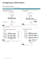
Configuring a DWX System Configuring an NT mode system Notes When determining the number of RMU-01 units to use, refer to the "Installation of Remote Control Unit RMU-01" (page 62) section and take the coverage area of the RMU-01 into consideration. When supplying power to the RMU-01 via PoE, refer to the diagrams in the "Power supply (PoE) for RMU-01" section. When operating from the receiver only One DWR-R01D unit Transmitters RMU-01 When operating from the receiver and a computer One DWR-R01D unit Transmitters RMU-01 (1 to 9) DWR-R01D Crossover cable Figure 5 Note Use a crossover cable to connect the DWR-R01D to the RMU-01. Multiple DWR-R01D units (2 to 41) Transmitters DWR-R01D DWR-R01D Hub Straight cable Straight cable Straight cable Figure 7 Note Use straight cables for all connections. Multiple DWR-R01D units (2 to 41) Transmitters DWR-R01D PC (1 to 6) Straight cable Straight cable DWR-R01D Straight cable RMU-01 (1 to 9) Hub Straight cable Figure 6 Note Use straight cables for all connections. DWR-R01D Straight cable Straight cable Hub RMU-01 (1 to 9) Straight cable Figure 8 Note Use straight cables for all connections. PC (1 to 6) Network System Configuration 59
-
 1
1 -
2
-
3
-
4
-
5
-
6
-
7
-
8
-
9
-
10
-
11
-
12
-
13
-
14
-
15
-
16
-
17
-
18
-
19
-
20
-
21
-
22
-
23
-
24
-
25
-
26
-
27
-
28
-
29
-
30
-
31
-
32
-
33
-
34
-
35
-
36
-
37
-
38
-
39
-
40
-
41
-
42
-
43
-
44
-
45
-
46
-
47
-
48
-
49
-
50
-
51
-
52
-
53
-
 54
54 -
 55
55 -
 56
56 -
 57
57 -
 58
58 -
 59
59 -
 60
60 -
 61
61 -
 62
62 -
 63
63 -
 64
64 -
65
-
66
-
67
-
68
-
69
-
70
-
71
-
72
-
73
-
74
-
75
-
76
-
77
-
78
-
79
-
80
-
81
-
82
 |
 |
