Sony DWTP01/E4250 Product Information Document (Digirtal Wireless System Integ - Page 46
Step 1, Channel Plan Selection
 |
View all Sony DWTP01/E4250 manuals
Add to My Manuals
Save this manual to your list of manuals |
Page 46 highlights
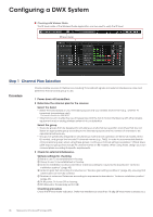
Configuring a DWX System Checking with Wireless Studio The RF level meter of the Wireless Studio application can be used to verify the RF level. RF level meter Step 1 Channel Plan Selection Procedure Check possible sources of interference including TV broadcast signals and external interference noise and determine the band and group to use. 1 Power down all transmitters. 2 Determine the channel plan for the receiver. Select the band Select the band based on your intended purpose and your wireless environment (e.g., whether TV broadcast transmissions exist). *The band is fixed for the DWR-S01D. Take factors such as effective use of frequencies and the risk of mutual interference with other wireless equipment and/or analog wireless systems into consideration. Select the group There are groups that are designed for simultaneous multi-channel operation and others that are not. Select an appropriate group according to the intended purpose and the number of channels to be operated simultaneously. Groups not specifically designed for simultaneous multi-channel operation are 00 for US models, 00 for EU models, and groups that include TV channel names (e.g., TV62). In order to accommodate flexible channel planning even when using these groups, continuous channel setting is possible in 125-kHz steps (25-K steps for groups that include TV channel names on EU models). When using these, design your own channel plans according to specific requirements. 3 Check for external interference. Sample settings for checking Band to use: To be established in this step. Group to use: To be established in this step. Antenna installation location/orientation: Install according to requirements described in "Antenna installation position" (page 43). Antenna gain: Set according to instructions in "Booster gain setting conditions" (page 44), ensuring that cable losses can be fully covered. Number of antennas: Determine according to requirements described in "Antenna installation position" (page 43). TX RF power: TX to be OFF in this step. RX attenuator: Provisionally set to 0 dB. Checking procedure Check the RF level meter indication. Verify that interference is less than 10 dBμ (RF level meter is always out.). 46 Making and Checking RF Settings (UHF)
-
 1
1 -
2
-
3
-
4
-
5
-
6
-
7
-
8
-
9
-
10
-
11
-
12
-
13
-
14
-
15
-
16
-
17
-
18
-
19
-
20
-
21
-
22
-
23
-
24
-
25
-
26
-
27
-
28
-
29
-
30
-
31
-
32
-
33
-
34
-
35
-
36
-
37
-
38
-
39
-
40
-
 41
41 -
 42
42 -
 43
43 -
 44
44 -
 45
45 -
 46
46 -
 47
47 -
 48
48 -
 49
49 -
 50
50 -
 51
51 -
52
-
53
-
54
-
55
-
56
-
57
-
58
-
59
-
60
-
61
-
62
-
63
-
64
-
65
-
66
-
67
-
68
-
69
-
70
-
71
-
72
-
73
-
74
-
75
-
76
-
77
-
78
-
79
-
80
-
81
-
82
 |
 |
