Rane HAL1x Design Guide - Page 28
The Parts of a RAD, Label, XLR Tab, Input/Output jacks, Sig/OL LED, Power LED, Comm LED, Audio Rx LED - manual
 |
View all Rane HAL1x manuals
Add to My Manuals
Save this manual to your list of manuals |
Page 28 highlights
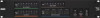
HAL SYSTEM DESIGN GUIDE The Parts of a RAD Following is an illustration of the front of a typical RAD, accompanied by descriptions of the RAD's various hardware features: 1. Label: a location on the RAD for inserting a custom label. One possible use of this label is to identify the channel number associated with the corresponding jack. 2. XLR Tab: push tab for releasing a microphone cable. If you do not need this tab, you should remove it before installing the RAD. For more information, see the RAD installation instructions beginning on page 1. 3. Input/Output jacks: the actual jacks to which you connect the appropriate audio device(s). The jacks differ based on the RAD model. 4. Sig/OL LED: displays a green light when an audio signal is detected, displays a red light when the channel is experiencing a signal overload. 5. Power LED: displays a solid green when the RAD is receiving power, displays solid red if the voltage received is lower than expected. 6. Comm LED: displays a solid green when the RAD detects two things-the communication pair of wires and that communication is established between the HAL and RAD. The light displays solid red if the RAD cannot communicate with the HAL. This is likely due to a problem with the communications pair of wires. 7. Audio Rx LED: displays solid green when the RAD detects that the pair of wires for receiving audio is functioning properly, regardless of the RAD model. Displays red if there is a problem. 8. Audio Tx LED: displays solid green if communication with the HAL has been established and the HAL informs the RAD of the Tx Audio lock. Displays solid red if there is a problem communicating with the RAD or if there is a problem with the Audio Tx pair of wires. 9. Light sensor: detects the amount of light in the room and dims or brightens all LEDs appropriately-primarily to prevent the LEDs from glowing in a darkened room like cat eyes on Halloween. Note that you cannot turn these LEDs off manually. This is by design. We wanted to avoid the possibility of someone erroneously thinking the RAD is defective (because the power light is off) and attempting to replace it unnecessarily. 24
-
 1
1 -
2
-
3
-
4
-
5
-
6
-
7
-
8
-
9
-
10
-
11
-
12
-
13
-
14
-
15
-
16
-
17
-
18
-
19
-
20
-
21
-
22
-
 23
23 -
 24
24 -
 25
25 -
 26
26 -
 27
27 -
 28
28 -
 29
29 -
 30
30 -
 31
31 -
 32
32 -
 33
33 -
34
-
35
-
36
-
37
-
38
-
39
-
40
-
41
-
42
-
43
-
44
-
45
-
46
-
47
-
48
-
49
-
50
-
51
-
52
-
53
-
54
-
55
-
56
-
57
-
58
-
59
-
60
-
61
-
62
-
63
-
64
-
65
-
66
-
67
-
68
-
69
-
70
-
71
-
72
-
73
-
74
-
75
-
76
-
77
-
78
-
79
-
80
-
81
-
82
-
83
-
84
-
85
-
86
-
87
-
88
-
89
-
90
-
91
-
92
-
93
-
94
-
95
-
96
-
97
-
98
-
99
-
100
-
101
-
102
-
103
-
104
-
105
-
106
-
107
-
108
-
109
-
110
-
111
-
112
-
113
-
114
-
115
-
116
-
117
-
118
-
119
-
120
-
121
-
122
-
123
-
124
-
125
-
126
-
127
-
128
-
129
-
130
-
131
-
132
-
133
-
134
-
135
-
136
-
137
-
138
-
139
-
140
-
141
-
142
-
143
-
144
-
145
-
146
-
147
-
148
-
149
-
150
-
151
-
152
-
153
-
154
-
155
-
156
-
157
-
158
-
159
-
160
-
161
-
162
-
163
-
164
-
165
-
166
-
167
-
168
-
169
-
170
-
171
-
172
-
173
-
174
-
175
-
176
-
177
-
178
-
179
-
180
-
181
-
182
-
183
-
184
-
185
-
186
-
187
-
188
-
189
-
190
-
191
-
192
-
193
-
194
-
195
-
196
 |
 |
