Invacare CXE Owners Manual - Page 40
Installing 3-Inch Extension
 |
View all Invacare CXE manuals
Add to My Manuals
Save this manual to your list of manuals |
Page 40 highlights
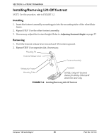
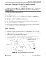
SECTION 5-FRONT RIGGINGS Installing 3-Inch Extension NOTE: For this procedure, refer to FIGURE 5.7. NOTE: Make sure to note position of hardware before disassembly of the footrest. NOTE: If using any type of extension with the adjustable angle footplate, refer to Installing Adjustable Angle Flip‐Up Footplate Hinge on page 38 or Adjusting Adjustable Angle Flip‐Up Footplates on page 39. 1. Remove any accessories that are attached to the footrests. 2. Remove the socket bolt, coved washer and locknut that secure the footplate to the footrest support. 3. Insert the 3‐inch extension into the footrest support and align the mounting holes. 4. Secure the 3‐inch extension to the footrest support with new hex bolt, washer and locknut. 5. Position the footplate at the desired height. NOTE: DO NOT overtighten. Footrest must be able to rotate upward from the horizontal to vertical position. 6. Reinstall the socket bolt through the mounting holes of the footplate and footrest support. 7. Secure the footplate to the footrest support with the coved washer and locknut. Locknut Footrest Support Washer Hex Bolt 3-inch Extension Socket Bolt, Coved Washer and Locknut FIGURE 5.7 Installing 3-Inch Extension Compass™XE and Allegro® 40 Part No 1127114
-
 1
1 -
2
-
3
-
4
-
5
-
6
-
7
-
8
-
9
-
10
-
11
-
12
-
13
-
14
-
15
-
16
-
17
-
18
-
19
-
20
-
21
-
22
-
23
-
24
-
25
-
26
-
27
-
28
-
29
-
30
-
31
-
32
-
33
-
34
-
 35
35 -
 36
36 -
 37
37 -
 38
38 -
 39
39 -
 40
40 -
 41
41 -
 42
42 -
 43
43 -
 44
44 -
 45
45 -
46
-
47
-
48
-
49
-
50
-
51
-
52
-
53
-
54
-
55
-
56
-
57
-
58
-
59
-
60
-
61
-
62
-
63
-
64
-
65
-
66
-
67
-
68
-
69
-
70
-
71
-
72
-
73
-
74
-
75
-
76
-
77
-
78
-
79
-
80
-
81
-
82
-
83
-
84
-
85
-
86
-
87
-
88
-
89
-
90
-
91
-
92
-
93
-
94
-
95
-
96
-
97
-
98
-
99
-
100
-
101
-
102
-
103
-
104
-
105
-
106
-
107
-
108
-
109
-
110
-
111
-
112
-
113
-
114
-
115
-
116
-
117
-
118
-
119
-
120
-
121
-
122
-
123
-
124
-
125
-
126
-
127
-
128
-
129
-
130
-
131
-
132
-
133
-
134
-
135
-
136
-
137
-
138
-
139
-
140
 |
 |
