D-Link DGS-3312SR Product Manual - Page 17
Rear Panel Description, RPS Connector, Plug-in Modules, DEM-340T 1000BASE-T Module
 |
View all D-Link DGS-3312SR manuals
Add to My Manuals
Save this manual to your list of manuals |
Page 17 highlights
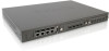
DGS-3312SR Gigabit Layer 3 Switch Stack ID The Switch includes a digital indicator to indicate the Switch status in a stacked Switch group. An "F" indicates the Switch is acting in the capacity of a master Switch of a stacked group of DGS-3312SR/DES-3226S Switches. The remaining slave Switches in the group will display a corresponding stack number (1-C) to indicate the logical position of the slave Switch in the stacked group. See the discussion of Switch Stacking below for more information on stacking DGS-3312SR/DES-3226S Switches. NOTICE: Do not connect the stacked Switch group to the network until you have properly configured all Switches for stacking. An improperly configured Switch stack can cause a broadcast storm. Rear Panel Description The rear panel of the Switch contains an AC power connector. Figure 1- 4. Rear panel view of the Switch The AC power connector is a standard three-pronged connector that supports the power cord. Plug-in the female connector of the provided power cord into this socket, and the male side of the cord into a power outlet. The Switch automatically adjusts its power setting to any supply voltage in the range from 100 ~ 240 VAC at 50 ~ 60 Hz. RPS Connector Connect the optional external redundant power supply to the RPS connector. If the Switch's internal power unit fails, the redundant power system automatically supplies power to the Switch for uninterrupted operation. The Switch supports the D-Link RPS-200 or RPS-500 redundant power supply units. Plug-in Modules The DGS-3312SR Switch is able to accommodate optional plug-in modules in order to increase functionality and performance. Two modules may be installed and used in combination with any of the three available modules. Plug-in modules must be purchased separately. DEM-340T 1000BASE-T Module Figure 1- 5. 1000BASE-T Four-port module • Front-panel module • Connects to 1000BASE-T devices • LED indicators for Link/Activity 4
-
 1
1 -
2
-
3
-
4
-
5
-
6
-
7
-
8
-
9
-
10
-
11
-
 12
12 -
 13
13 -
 14
14 -
 15
15 -
 16
16 -
 17
17 -
 18
18 -
 19
19 -
 20
20 -
 21
21 -
 22
22 -
23
-
24
-
25
-
26
-
27
-
28
-
29
-
30
-
31
-
32
-
33
-
34
-
35
-
36
-
37
-
38
-
39
-
40
-
41
-
42
-
43
-
44
-
45
-
46
-
47
-
48
-
49
-
50
-
51
-
52
-
53
-
54
-
55
-
56
-
57
-
58
-
59
-
60
-
61
-
62
-
63
-
64
-
65
-
66
-
67
-
68
-
69
-
70
-
71
-
72
-
73
-
74
-
75
-
76
-
77
-
78
-
79
-
80
-
81
-
82
-
83
-
84
-
85
-
86
-
87
-
88
-
89
-
90
-
91
-
92
-
93
-
94
-
95
-
96
-
97
-
98
-
99
-
100
-
101
-
102
-
103
-
104
-
105
-
106
-
107
-
108
-
109
-
110
-
111
-
112
-
113
-
114
-
115
-
116
-
117
-
118
-
119
-
120
-
121
-
122
-
123
-
124
-
125
-
126
-
127
-
128
-
129
-
130
-
131
-
132
-
133
-
134
-
135
-
136
-
137
-
138
-
139
-
140
-
141
-
142
-
143
-
144
-
145
-
146
-
147
-
148
-
149
-
150
-
151
-
152
-
153
-
154
-
155
-
156
-
157
-
158
-
159
-
160
-
161
-
162
-
163
-
164
-
165
-
166
-
167
-
168
-
169
-
170
-
171
-
172
-
173
-
174
-
175
-
176
-
177
-
178
-
179
-
180
-
181
-
182
-
183
-
184
-
185
-
186
-
187
-
188
-
189
-
190
-
191
-
192
-
193
-
194
-
195
-
196
-
197
-
198
-
199
-
200
-
201
-
202
-
203
-
204
-
205
-
206
-
207
-
208
-
209
-
210
-
211
-
212
-
213
-
214
-
215
-
216
-
217
-
218
-
219
-
220
-
221
-
222
-
223
-
224
-
225
-
226
-
227
-
228
-
229
-
230
-
231
-
232
-
233
-
234
-
235
-
236
-
237
-
238
-
239
-
240
-
241
-
242
-
243
-
244
 |
 |
