Cisco C1861-SRST-B/K9 Hardware Installation Guide - Page 55
Verifying the Front Panel LED Indications, Verifying the Hardware Configuration
 |
UPC - 882658171147
View all Cisco C1861-SRST-B/K9 manuals
Add to My Manuals
Save this manual to your list of manuals |
Page 55 highlights
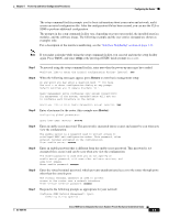
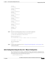
Chapter 5 Power-Up and Initial Configuration Procedures Configuring the Router To use the CLI to configure the router, see the "Initial Configuration Using the Cisco CLI-Manual Configuration" section on page 5-7. Note If the rommon 1> prompt appears, your system has booted in ROM monitor mode. Verifying the Front Panel LED Indications The front-panel indicator LEDs described in Table 5-1 provide power, activity, and status information useful during power up. For more detailed information about the LEDs, see the "LED Indicators" section on page 1-4. Table 5-1 LED Indicators for the Cisco 1800 Series Fixed-Configuration Router LED Label LED Color or State Meaning SYS OK Solid green System is operating normally Blinking green System is booting or is in ROM monitor mode POE1 Off Green Power is off, or there is a power fault Inline power supply is installed and operating normally Amber Inline power supply fault Off Inline power supply is not installed CF Blinking green or solid green CompactFlash memory is being accessed; do not eject Off CompactFlash memory is not being accessed; OK to eject 1. Inline power is a field-upgradable option on Cisco 1800 series fixed-configuration routers; inline power is not installed by default. Verifying the Hardware Configuration To display and verify the hardware features, enter the following commands: • show version-Displays the system hardware version; the installed software version; the names and sources of configuration files; the boot images; and the amount of installed DRAM, NVRAM, and flash memory. • show diag-Lists and displays diagnostic information about the controllers and interface processors. Configuring the Router This section includes the following topics: • Initial Configuration Using Cisco Router and Security Device Manager • Initial Configuration Using the Setup Command Facility • Initial Configuration Using the Cisco CLI-Manual Configuration • Verifying the Initial Configuration OL-6425-03 Cisco 1800 Series Integrated Services Routers (Fixed) Hardware Installation Guide 5-3
-
 1
1 -
2
-
3
-
4
-
5
-
6
-
7
-
8
-
9
-
10
-
11
-
12
-
13
-
14
-
15
-
16
-
17
-
18
-
19
-
20
-
21
-
22
-
23
-
24
-
25
-
26
-
27
-
28
-
29
-
30
-
31
-
32
-
33
-
34
-
35
-
36
-
37
-
38
-
39
-
40
-
41
-
42
-
43
-
44
-
45
-
46
-
47
-
48
-
49
-
 50
50 -
 51
51 -
 52
52 -
 53
53 -
 54
54 -
 55
55 -
 56
56 -
 57
57 -
 58
58 -
 59
59 -
 60
60 -
61
-
62
-
63
-
64
-
65
-
66
-
67
-
68
-
69
-
70
-
71
-
72
-
73
-
74
-
75
-
76
-
77
-
78
-
79
-
80
-
81
-
82
 |
 |
