Adaptec AHA-2930 Installation Guide - Page 4
Installing Internal SCSI Devices - manual
 |
View all Adaptec AHA-2930 manuals
Add to My Manuals
Save this manual to your list of manuals |
Page 4 highlights
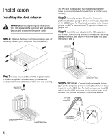
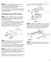
Step 6: Make sure that all SCSI devices have unique SCSI ID's from 0 to 6. (Refer to your device documentation for SCSI ID settings and instructions on manually changing the default settings.) If you are installing external SCSI devices only, replace the computer chassis cover and skip to Installing External SCSI Devices on page 4. Installing Internal SCSI Devices Step 1: Install or enable terminators on the internal SCSI device that you plan to connect to the end of the internal cable. Then remove or disable terminators on all other internal devices. On most internal SCSI devices, you control termination by setting a jumper or a switch, or by physically removing or installing a resistor module(s). Refer to the device's documentation to determine how to enable or disable termination on your particular device. Pin-1 of the connector is usually designated by a small triangle (v), or a "1" on the connector. Colored Stripe 50-pin SCSI Ribbon Cable Pin 1 Internal SCSI Connector Step 4: Plug the other end of the 50-pin internal SCSI cable into one of the connectors on the last internal SCSI device in the chain. (This device must be terminated.) Make sure the colored stripe on the side of the cable is aligned with pin-1 of the SCSI device's connector. Pin 1 Termination Enabled Termination Disabled Step 2: Install and mount each internal SCSI device inside your computer. (Refer to your computer and device documentation for instructions.) If you purchased your AHA-2930B as part of an Adaptec kit, the kit includes one 50-pin internal SCSI cable that allows you to connect up to two internal SCSI devices. Step 3: Plug one end of your 50-pin internal SCSI cable into the host adapter's internal SCSI connector. To connect more than two internal devices, use a SCSI cable with enough connectors to accommodate all of your devices. Make sure that the colored stripe on one side of the cable is aligned with pin-1 of the host adapter's connector. Colored Stripe Internal SCSI Device Step 5: Plug the remaining cable connectors into any remaining internal devices. (These devices must not be terminated.) 3
-
 1
1 -
 2
2 -
 3
3 -
 4
4 -
 5
5 -
 6
6 -
 7
7 -
 8
8 -
 9
9 -
 10
10 -
11
-
12
-
13
-
14
-
15
-
16
 |
 |
