Panasonic AJSDC915 AJSDC915 User Guide - Page 62
Changing The Display Mode, Setting The Marker Displays, Or Center Mark.
 |
View all Panasonic AJSDC915 manuals
Add to My Manuals
Save this manual to your list of manuals |
Page 62 highlights
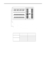
Status Displays Inside the Viewfinder Screen Changing the Display Mode The display mode setting appears on the "VF DISPLAY" SUB menu page of MAIN menu screen 2 of 4. 1 Set the MENU SET/OFF switch to the SET position while the SHIFT/ITEM button and UP button are held down together. 2 Press the PAGE button to display the MAIN menu screen 2 of 4. 3 Press the SHIFT/ITEM button to move the cursor to the "VF DISPLAY" position. 4 Press the UP or DOWN button to open the VF DISPLAY page. ¢| V F D I S P L A Y { D I SP COND I T I ON : NORMA L D I S P MODE :3 SA F E T Y ZONE :3 CENTER MARK : ON V F OUT :Y VF DTL :2 ZEBRA 1 DETECT : 0 7 0% ZEBRA 2 DETECT : 0 8 5% Z EBRA 2 : SPOT 5 0M I ND I CA T I ON : ON L OW L I GH T L V L : 4 5% 5 Press the SHIFT/ITEM button to move the cursor to the "DISP MODE" position. 6 Press the UP (or DOWN) button to switch to the desired display mode. 7 When the menu operations are completed, set the MENU SET/OFF switch to the OFF position. The setting menu is cleared from the viewfinder screen, and the unit's current statuses appear at the top and bottom of the viewfinder screen. Setting the Marker Displays ON or OFF is selected for the center mark and safety zone mark display and a ratio of 80% or 90% of the total screen area is set for the safety zone range on the "VF DISPLAY" SUB menu page of MAIN menu screen 2 of 4. 1 Perform steps 1 to 4 under "Changing the Display Mode" described above so that the VF DISPLAY page appears on the viewfinder screen, and align the cursor with SAFETY ZONE or CENTER MARK. 2 Press the UP (or DOWN) button to switch to the desired display mode. 3 When the menu operations are completed, set the MENU SET/OFF switch to the OFF position. The setting menu is cleared from the viewfinder screen, and the unit's current statuses appear at the top and bottom of the viewfinder screen. - 62 -
-
 1
1 -
2
-
3
-
4
-
5
-
6
-
7
-
8
-
9
-
10
-
11
-
12
-
13
-
14
-
15
-
16
-
17
-
18
-
19
-
20
-
21
-
22
-
23
-
24
-
25
-
26
-
27
-
28
-
29
-
30
-
31
-
32
-
33
-
34
-
35
-
36
-
37
-
38
-
39
-
40
-
41
-
42
-
43
-
44
-
45
-
46
-
47
-
48
-
49
-
50
-
51
-
52
-
53
-
54
-
55
-
56
-
 57
57 -
 58
58 -
 59
59 -
 60
60 -
 61
61 -
 62
62 -
 63
63 -
 64
64 -
 65
65 -
 66
66 -
 67
67 -
68
-
69
-
70
-
71
-
72
-
73
-
74
-
75
-
76
-
77
-
78
-
79
-
80
-
81
-
82
-
83
-
84
-
85
-
86
-
87
-
88
-
89
-
90
-
91
-
92
-
93
-
94
-
95
-
96
-
97
-
98
-
99
-
100
-
101
-
102
-
103
-
104
-
105
-
106
-
107
-
108
-
109
-
110
-
111
-
112
-
113
-
114
-
115
-
116
-
117
-
118
-
119
-
120
-
121
-
122
-
123
-
124
-
125
-
126
-
127
-
128
-
129
-
130
-
131
-
132
-
133
-
134
-
135
-
136
-
137
-
138
-
139
-
140
-
141
-
142
-
143
-
144
-
145
-
146
-
147
-
148
-
149
-
150
-
151
-
152
-
153
-
154
-
155
-
156
-
157
-
158
-
159
-
160
 |
 |
