LiftMaster LJ8950W LJ8950W Manual
LiftMaster LJ8950W Manual
 |
View all LiftMaster LJ8950W manuals
Add to My Manuals
Save this manual to your list of manuals |
LiftMaster LJ8950W manual content summary:
- LiftMaster LJ8950W | LJ8950W Manual - Page 1
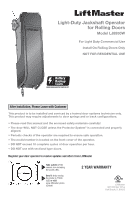
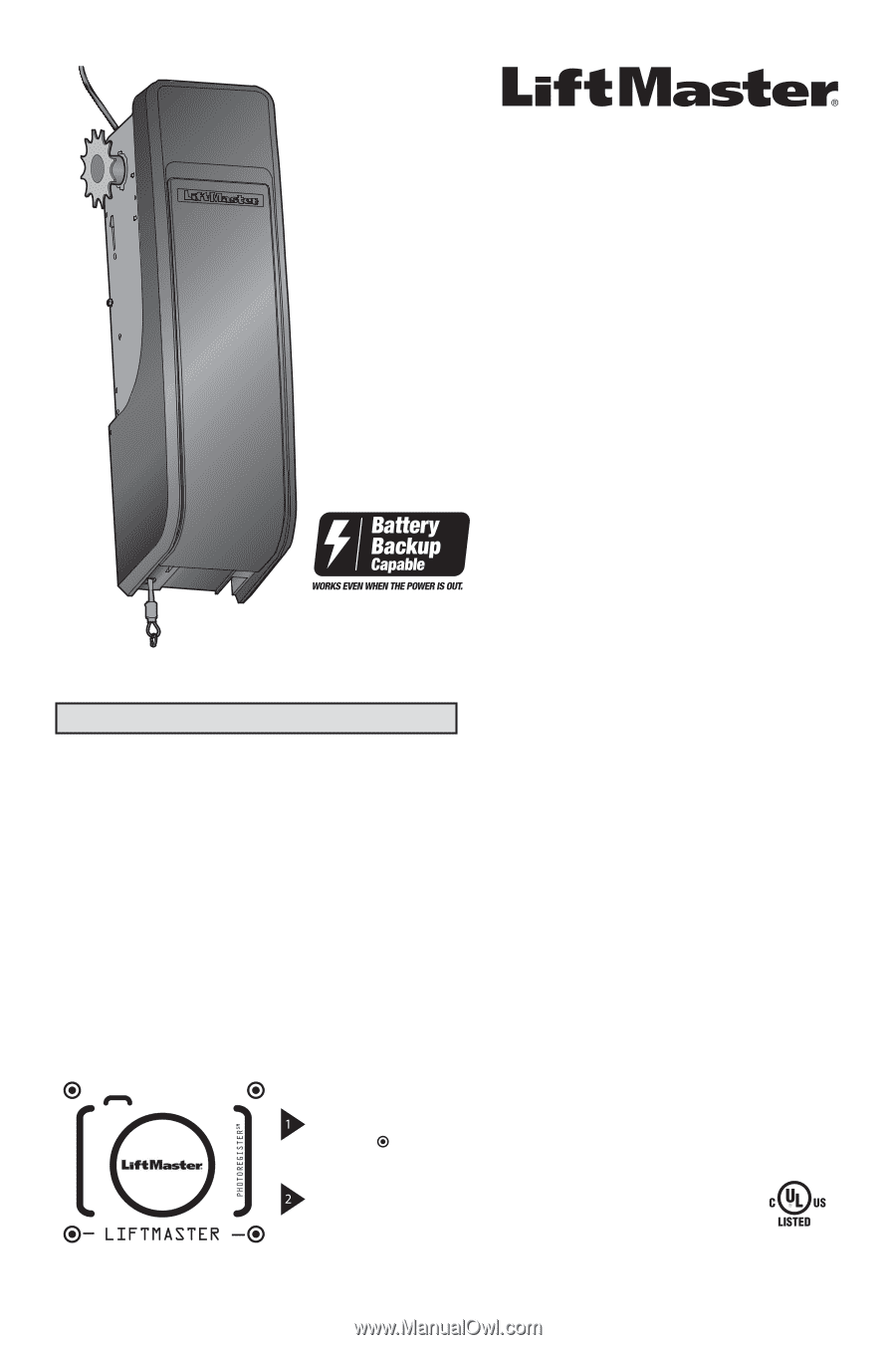
Light-Duty Jackshaft Operator for Rolling Doors Model LJ8950W For Light Duty Commercial Use Install On Rolling Doors Only NOT FOR RESIDENTIAL USE After Installation, Please Leave with Customer This product is to be installed and serviced by a trained door systems technician only. This product may - LiftMaster LJ8950W | LJ8950W Manual - Page 2
Install the Single Button Control Station 12 Install The Protector System 13 Install the Light Curtain (Not Provided 16 Connect Power 17 Install safe service provided it is installed, operated, maintained and tested in strict accordance with the instructions and warnings contained in this manual. - LiftMaster LJ8950W | LJ8950W Manual - Page 3
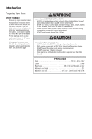
damage. • DO NOT exceed 10 complete cycles of door operation per hour. • DO NOT run operator if the door is locked. • Chain guard to be installed where the drive chain is exposed lower than 8 feet (2.5 m). SPECIFICATIONS Volts 120 Vac - 60 Hz, ONLY Current 1.5 AMP Rated Load 385 in. lb./sec. 10 - LiftMaster LJ8950W | LJ8950W Manual - Page 4
Conductor Bell Wire White and White/Red Mounting Bracket (4) Single Button Control Station Safety Reversing Sensor Bracket (2) 12 Tooth Drive brackets (Model 041A5281-1) or wood blocks: Depending upon building construction, extension brackets or wood blocks may be needed to install the safety - LiftMaster LJ8950W | LJ8950W Manual - Page 5
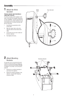
be installed on either side of the door. The drive sprocket can be installed on the right or left side of the operator depending on your installation. The the wall with the mounting brackets provided. An optional mounting bracket Model 3950MB is available for purchase, see Accessories page 30. 1. - LiftMaster LJ8950W | LJ8950W Manual - Page 6
the risk of SEVERE INJURY or DEATH: 1. READ AND FOLLOW ALL INSTALLATION WARNINGS 8. NEVER wear watches, rings or loose clothing while AND INSTRUCTIONS. installing or servicing operator. They could be caught in 2. Install door operator ONLY on properly balanced and door or operator mechanisms - LiftMaster LJ8950W | LJ8950W Manual - Page 7
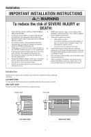
using the optional mounting bracket Model 3950MB. MINIMUM SHAFT LENGTH The door shaft must extend past the drum bracket a minimum of 1.5" (3.8 cm) (2.5" [6.3 cm] recommended) for installing the door sprocket. Drum Door 2.5" (6.3 cm) Door Shaft Drum Bracket Door Guide 11" (27.9 cm) Min. Clearance - LiftMaster LJ8950W | LJ8950W Manual - Page 8
of 11" (27.9 cm) clearance on the outside of the door guide is required for outside mounting. A minimum of 3.75" (9.5 cm) clearance is required for inside mounting. If the door brackets interfere with door operator installation, move the door brackets away from the door assembly to provide room in - LiftMaster LJ8950W | LJ8950W Manual - Page 9
MUST use the door sprocket provided in order for the door operator to function correctly. The instructions below describe the general installation procedure. Refer to the door manufacturer for specific instructions regarding your door. LIVE SHAFT 1. Slide the door sprocket onto the end of the door - LiftMaster LJ8950W | LJ8950W Manual - Page 10
Installation 2 Mount the Door Operator MOUNTING OPTIONS There are three options for mounting the door operator: • Standard wall mount using the brackets included with the door operator. • Outside bracket mount using the optional mounting bracket Model call an authorized service technician if door - LiftMaster LJ8950W | LJ8950W Manual - Page 11
provided). 6. Tighten the drive sprocket bolts using a 5/32" Allen wrench. If the operator is mounted below 8 ft. (2.5 m), chain guard model 3950CGJ must be installed to protect against possible injury, see accessories page 30. LIVE SHAFT DOOR Chain DEAD SHAFT DOOR Chain Mounting Hardware (not - LiftMaster LJ8950W | LJ8950W Manual - Page 12
knot. NOTE: If it is necessary to cut the rope, heat seal the cut end with a match or lighter to prevent unraveling. 4 Install the Single Button Control Station Install the door control within sight of the door, out of reach of children, at a minimum height of 5 ft. (1.5 m) above floors, landings - LiftMaster LJ8950W | LJ8950W Manual - Page 13
the door operator will move in the down direction. This is a required safety device and cannot be disabled. The LiftMaster Light Curtain LC36A may be installed as an optional secondary safety device, see page 16. IMPORTANT INFORMATION ABOUT THE SAFETY REVERSING SENSORS When properly connected and - LiftMaster LJ8950W | LJ8950W Manual - Page 14
right and left assemblies to the same distance out from the mounting surface. Make sure all door hardware obstructions are cleared. OPTION B: FLOOR INSTALLATION 1. Use wood blocks or extension brackets (see Accessories) to elevate sensor brackets so the lenses will be no higher than 6" (15 cm) above - LiftMaster LJ8950W | LJ8950W Manual - Page 15
Installation MOUNTING THE SAFETY REVERSING SENSORS 1. Slide a 1/4"-20x1/2" carriage bolt head into the slot on each sensor. 2. Use wing nuts to fasten safety reversing sensors to - LiftMaster LJ8950W | LJ8950W Manual - Page 16
(Not Provided) The following are general instructions for a typical installation, refer to the complete instructions included with the Light Curtain. The plug-in power supply accessory (model 100MAPS) is required to power the Light Curtain. LiftMaster Light Curtain (Model LC-36A) is an ancillary - LiftMaster LJ8950W | LJ8950W Manual - Page 17
pin. This plug will only fit into a grounding type outlet. If the plug doesn't fit into the outlet you have, contact a qualified electrician to install the proper outlet. There are two options for connecting power: OPTION A: TYPICAL WIRING 1. Plug in the door operator into a grounded outlet. 2. DO NOT - LiftMaster LJ8950W | LJ8950W Manual - Page 18
ENSURE THE SAFETY REVERSING SENSORS ARE ALIGNED The door will not close if the sensors have not been installed and aligned correctly. When the light beam is obstructed or misaligned while the door is closing, the door will reverse. If the door is already - LiftMaster LJ8950W | LJ8950W Manual - Page 19
Installation 8 Install the Battery Backup (Not Provided) When in Battery Backup mode, myQ Smartphone Control service or maintenance. • Use ONLY LiftMaster part # 485LM for replacement battery. • DO NOT dispose of battery in fire. Battery may explode. Check with local codes for disposal instructions. - LiftMaster LJ8950W | LJ8950W Manual - Page 20
through a complete up and down cycle using the remote control or the UP and DOWN buttons. If you are unable to operate the door up and down, repeat the steps for above. Without a properly installed safety reversal system, persons (particularly small children) could be SERIOUSLY INJURED or KILLED by - LiftMaster LJ8950W | LJ8950W Manual - Page 21
If the door stops but does not reverse: 1. Review the installation instructions provided to insure all steps were followed; 2. Repeat Program flat) 3 Test the Protector System 1. Press the control station button to open the door. 2. Place the operator carton in the path of the door. - LiftMaster LJ8950W | LJ8950W Manual - Page 22
be fully closed if possible. Pull down on the emergency release handle until a click noise is heard from the door operator and lift the door manually. To reconnect the door to the door operator, pull the emergency release handle straight down a second time until a click noise is heard from the door - LiftMaster LJ8950W | LJ8950W Manual - Page 23
WARNINGS AND INSTRUCTIONS. 2. ALWAYS keep remote controls out of reach of children. NEVER permit children to operate or play with door control push buttons or remote , disconnect ALL electric and battery power BEFORE performing ANY service or maintenance. 13. This door operator system is equipped - LiftMaster LJ8950W | LJ8950W Manual - Page 24
are not installed, or are misaligned, the door will not close from a remote control. However, you can close the door if you hold the button on the door door will reverse. However, you can close the door if you hold the button on the door control or keyless entry until the door is fully closed. - LiftMaster LJ8950W | LJ8950W Manual - Page 25
refer to the instructions provided with the accessory or visit LiftMaster.com. If model, and year of your vehicle. Visit www.homelink.com for additional information. To Erase the Memory ERASE ALL REMOTE CONTROLS AND KEYLESS ENTRIES 1. Press and hold the LEARN button on door operator until the learn - LiftMaster LJ8950W | LJ8950W Manual - Page 26
Maintenance Care of Your Door Operator MAINTENANCE SCHEDULE Once a Month • Manually operate door. If it is unbalanced or binding, call a residential installation. This equipment generates, uses and can radiate radio frequency energy and, if not installed and used in accordance with the instructions, - LiftMaster LJ8950W | LJ8950W Manual - Page 27
Button DOWN Button DIAGNOSTIC CODE SYMPTOM Up Arrow Down Arrow Flash(es) Flash(es) SOLUTION 1 1 The door operator will not close. Safety reversing sensors are not installed Replace travel module if necessary. Manually open and close the door. operator again. If problem persists, replace logic - LiftMaster LJ8950W | LJ8950W Manual - Page 28
buttons are off. • Remove the bell wire from the single button control station terminals and operate from the remote only. If this solves the problem, the single button sensors are properly installed, aligned and manually. A properly balanced door will stay in any point of travel while being supported - LiftMaster LJ8950W | LJ8950W Manual - Page 29
Repair Parts Installation Parts 2 3 5 9 1 4 8 6 7 KEY PART NO. NO. 1 041A4582 2 041B4494-1 3 041B6228 4 041A5034 DESCRIPTION kit Dead shaft sprocket kit Drive sprocket kit Drive chain (#48) NOT SHOWN Owner's manual Door Operator Parts 2 1 6 5 3 4 KEY PART NO. NO. DESCRIPTION - LiftMaster LJ8950W | LJ8950W Manual - Page 30
Single button control station G893LM 3-Button Remote inside the door guides. 3950CGJ Chain installation and service information call: 1-800-528-9131 Or visit us online at: LiftMaster.com Before calling, please have the model number of the door operator. If you are calling about a troubleshooting - LiftMaster LJ8950W | LJ8950W Manual - Page 31
service léger Modèle LJ8950W Pour installation à usage commercial de service léger Installer sur des portes roulantes uniquement N'EST PAS DESTINÉ À UNE UTILISATION RÉSIDENTIELLE Après l'installation recevoir des mises à jour et des offres de LiftMaster SM Prenez une photo de l'icône d' - LiftMaster LJ8950W | LJ8950W Manual - Page 32
Fixer le pignon d'entraînement 5 Fixer les supports de montage 5 Installation 6 Introduction 6 Exigences pour porte avec arbre but d'offrir un service sûr à condition qu'il soit installé, utilisé, entretenu et mis à l'essai en stricte conformité avec les instructions et les avertissements - LiftMaster LJ8950W | LJ8950W Manual - Page 33
type à arbre mobile, l'arbre d'entraînement doit dépasser de 3,8 cm (1-1/2 de po) le support de montage de la porte. • Si l'actionneur est monté à moins de 2,5 m (8 pi) de hauteur, un carter de chaîne doit être installé pour prévenir les blessures. Se reporter à la page des accessoires. Pour éviter - LiftMaster LJ8950W | LJ8950W Manual - Page 34
de rallonge (modèle 041A52811) ou blocs de bois : Selon la construction du bâtiment, des supports de rallonge ou des cales en bois peuvent être nécessaires pour installer le détecteur inverseur de sécurité. Fixations : Le montage au sol du détecteur inverseur de sécurité nécessitera des fixations - LiftMaster LJ8950W | LJ8950W Manual - Page 35
installé sur chaque côté de la porte. Le pignon d'entraînement peut être installé du côté droit ou gauche de l'actionneur, selon l'installation. Boulon Boulon 2 Fixer les supports de montage L'actionneur peut être monté au mur avec les supports de montage fournis. Un support de montage en option de - LiftMaster LJ8950W | LJ8950W Manual - Page 36
LA POSE Pour réduire le risque de BLESSURES GRAVES, voire MORTELLES : 1. LIRE ET SUIVRE TOUS LES AVERTISSEMENTS ET amples durant l'installation ou l'entretien de l'actionneur. INSTRUCTIONS D'INSTALLATION. Ils pourraient être happés par la porte ou les 2. L'actionneur doit SEULEMENT être - LiftMaster LJ8950W | LJ8950W Manual - Page 37
du tambour de 3,8 cm (1,5 de po) au minimum (recommandé - 6,3 cm ou 2,5 de po) pour installer le pignon de la porte. Tambour Porte 6,3 cm (2,5 de po) Arbre de la porte Support de tambour Guide de la porte Dégagement minimal de 27,9 cm (11 po) Montage extérieur Dégagement minimal de 9,5 cm (3-3/4 de - LiftMaster LJ8950W | LJ8950W Manual - Page 38
sur l'extérieur du guide de porte est exigé pour le montage à l'extérieur. Un dégagement minimal de 9.5 cm (3,75 po) est exigé pour le montage à l'intérieur. Si les supports de montage interfèrent avec l'installation de l'actionneur de porte, déplacer les supports de porte à l'écart de l'assemblage - LiftMaster LJ8950W | LJ8950W Manual - Page 39
le pignon de porte fourni pour que l'actionneur de porte puisse fonctionner correctement. Les instructions ci-dessous décrivent la méthode d'installation générale. Consulter le fabricant de la porte pour des instructions particulières concernant votre porte. ARBRE MOBILE 1. Glisser le pignon de la - LiftMaster LJ8950W | LJ8950W Manual - Page 40
FOURNIS Position moyenne du pignon d'entraînement à 1,6 cm (5/8 de po) du guide de la porte Position intérieure du pignon d'entraînement à 2,5 cm (1 po) du guide de la porte Guide de la porte MONTAGE EXTÉRIEUR AVEC SUPPORT DE MONTAGE 3950MB EN OPTION Position intérieure du pignon d'entraînement - LiftMaster LJ8950W | LJ8950W Manual - Page 41
une clé Allen de 5/32 de po. Si l'actionneur est monté à moins de 2,5 m (8 pi), carter de chaîne de modèle 3950CGJ qui doit être installé pour prévenir les blessures potentielles, voir la page Accessoires 30. PORTE À ARBRE MOBILE Chaîne PORTE À ARBRE FIXE Chaîne Quincaillerie de montage (non - LiftMaster LJ8950W | LJ8950W Manual - Page 42
corde à l'aide d'un noeud simple. REMARQUE : Si la corde doit être coupée, brûler légèrement l'extrémité coupée pour empêcher qu'elle s'effiloche. 4 Installer le poste de commande à seul bouton Poser la commande de la porte dans un endroit où on pourra la voir de la porte de commercial, hors - LiftMaster LJ8950W | LJ8950W Manual - Page 43
Le rideau de lumière LiftMaster LC36A peut être installé comme dispositif de sécurité supports doivent être fixés fermement à une surface solide telle que la charpente du mur. On peut se procurer des supports . Aucune partie de la porte (ni les guides, les ressorts, les charnières, les rouleaux - LiftMaster LJ8950W | LJ8950W Manual - Page 44
plus de 15 cm (6 po) au-dessus du sol. Ils peuvent être posés de trois façons, suivant vos exigences, comme suit : OPTION A : INSTALLATION AU MUR 1. Placer le support contre le mur, les bras courbés étant dirigés vers la porte. S'assurer qu'il y a un dégagement suffisant et qu'aucun obstacle n'est - LiftMaster LJ8950W | LJ8950W Manual - Page 45
Installation MONTAGE DES DÉTECTEURS INVERSEURS DU SECURITIÉ 1. Faire glisser un boulon à tête bombée et collet carré de 1/4 de po-20 x 1/2 de po dans la fente de chaque détecteur. 2. Utiliser des écrous à oreilles pour fixer les détecteurs aux supports, avec les diffuseurs dirigés l'un vers l'autre - LiftMaster LJ8950W | LJ8950W Manual - Page 46
re (non fourni) Ces instructions générales conviennent à une installation typique, consulter les instructions complètes incluses avec le rideau de lumière. L'accessoire d'alimentation enfichable (modèle 100MAPS) est exigé pour alimenter le rideau de lumière. Le rideau de lumière LiftMaster (modèle LC - LiftMaster LJ8950W | LJ8950W Manual - Page 47
l'actionneru de porte est hors tension et couper l'alimentation du circuit AVANT de retirer le couvercle pour procéder à un branchement permanent. • L'installation et le câblage de la porte DOIVENT être conformes à TOUS les codes électriques et du bâtiment locaux. • Ne JAMAIS utiliser d'un cordon - LiftMaster LJ8950W | LJ8950W Manual - Page 48
S'ASSURER DE L'ALIGNEMENT DES DÉTECTEURS INVERSEURS DE SÉCURITÉ La porte ne se fermera pas si les détecteurs n'ont pas été installés et alignés correctement. Lorsque le faisceau de lumière est obstrué ou mal aligné quand la porte se ferme, cette dernière remontera. Si la - LiftMaster LJ8950W | LJ8950W Manual - Page 49
Installation 8 Installer la pile de secours (non fournie) Lorsque l'actionneur est en mode d' . • Utilisez UNIQUEMENT la pièce LiftMaster nº 485LM pour remplacer la pile. • Ne pas jeter PAS la pile au feu. La pile peut exploser. Pour connaître les instructions relatives à son élimination, vérifi - LiftMaster LJ8950W | LJ8950W Manual - Page 50
. Si on ne parvient pas à actionner la porte, répéter les étapes de la programmation de la course. Sans un système d'inversion de sécurité bien installé, des personnes (plus particulièrement les petits enfants) pourraient être GRIÈVEMENT BLESSÉES ou TUÉES par une porte qui se referme. • Un réglage - LiftMaster LJ8950W | LJ8950W Manual - Page 51
DOIT remonter quand elle entre en contact avec la planche. RÉGLAGE Si la porte arrête sa course, mais ne l'inverse pas : 1. Revoir les instructions d'installation fournies pour vérifier que toutes les étapes ont bien été suivies; 2. Répéter la programmation de la course de la porte (voir Étape 1 du - LiftMaster LJ8950W | LJ8950W Manual - Page 52
Réglages 4 Ouverture manuelle de la porte Désengager toutes les serrures de porte avant de procéder. Dans la mesure du possible, la porte doit être complètement fermée. Abaisser la poignée de déblocage vers le bas jusqu'à ce qu'un déclic se produise dans l'actionneur, puis soulever la porte - LiftMaster LJ8950W | LJ8950W Manual - Page 53
IMPORTANTES CONSIGNES DE SÉCURITÉ Pour réduire le risque de BLESSURES GRAVES, voire MORTELLES : 1. LIRE ET RESPECTER TOUS LES AVERTISSEMENTS ET TOUTES LES INSTRUCTIONS. 2. Garder EN TOUT TEMPS la télécommande hors de portée des enfants. NE PERMETTEZ JAMAIS à des enfants de faire fonctionner ou de - LiftMaster LJ8950W | LJ8950W Manual - Page 54
s'arrêtera et remontera jusqu'à la position entièrement ouverte. Si la porte est complètement ouverte et que les capteurs d'inversion ne sont pas installés ou sont mal alignés, la porte ne se ferme pas à partir d'une télécommande. Cependant, vous pouvez fermer la porte si vous maintenez le bouton de - LiftMaster LJ8950W | LJ8950W Manual - Page 55
accessoires supplémentaires, consultez les instructions qui accompagnent l'accessoire en question ou allez sur LiftMaster.com. Si votre véhicule est 1. Appuyer sur le bouton « LEARN » de l'actionneur et le maintenir enfoncé jusqu'à ce que la DEL du bouton « LEARN » s'éteigne (environ 6 secondes). - LiftMaster LJ8950W | LJ8950W Manual - Page 56
lubrifier l'actionneur de porte. Ne pas graisser les guides de la porte. AVERTISSEMENT : Cet appareil est conforme installé et utilisé conformément aux instructions, peut causer un brouillage nuisible aux communications radio. Cependant, rien ne garantit l'absence de brouillage dans une installation - LiftMaster LJ8950W | LJ8950W Manual - Page 57
pas. La porte glisse après qu'elle se soit complètement arrêtée. Aucun mouvement ni son. Les détecteurs inverseurs de sécurité ne sont pas installés, connectés, ou les fils sont coupés. Vérifier les fils du détecteur pour y déceler tout fil débranché ou coupé. Les détecteurs inverseurs de sécurité sont - LiftMaster LJ8950W | LJ8950W Manual - Page 58
constante, vérifier que les détecteurs inverseurs de sécurité ont été installés correctement et bien alignés, et qu'ils sont libres de toute obstruction Vérifier toute la quincaillerie de montage à l'actionneur de porte et/ou supports de montage de l'actionneur. L'actionneur de porte émet des bips : • - LiftMaster LJ8950W | LJ8950W Manual - Page 59
installation 2 3 5 9 1 4 8 6 7 NO. Nº DE PIÈCE DESCRIPTION CLÉ 1 041A4582 Poignée et corde de déclenchement d'urgence 2 041B4494-1 Fil de sonnerie blanc et blanc/rouge à 2 conducteurs 3 041B6228 Supports ) NON ILLUSTRÉS 114A5003 Manuel d'instructions Pièces de l'actionneur de - LiftMaster LJ8950W | LJ8950W Manual - Page 60
heures. 3950MB Support de Fixation : Le support peut être monté selon plusieurs configurations avec le moteur à l'extérieur ou à l'intérieur des guides de porte. curité ne sont pas correctement installés et alignés. Adresser la commande des pièces de réparationà : LiftMaster 2850 E. Drexel Rd., Suite
-
 1
1 -
 2
2 -
 3
3 -
 4
4 -
 5
5 -
 6
6 -
 7
7 -
8
-
9
-
10
-
11
-
12
-
13
-
14
-
15
-
16
-
17
-
18
-
19
-
20
-
21
-
22
-
23
-
24
-
25
-
26
-
27
-
28
-
29
-
30
-
31
-
32
-
33
-
34
-
35
-
36
-
37
-
38
-
39
-
40
-
41
-
42
-
43
-
44
-
45
-
46
-
47
-
48
-
49
-
50
-
51
-
52
-
53
-
54
-
55
-
56
-
57
-
58
-
59
-
60
 |
 |
For Light Duty Commercial Use
Install On Rolling Doors Only
NOT FOR RESIDENTIAL USE
Light-Duty Jackshaft Operator
for Rolling Doors
Model LJ8950W
LiftMaster
300 Windsor Drive
Oak Brook, IL 60523
•
Please read this manual and the enclosed safety materials carefully!
•
The door WILL NOT CLOSE unless the Protector System
®
is connected and properly
aligned.
•
Periodic checks of the operator are required to ensure safe operation.
•
The model number is located on the front cover of the operator.
•
DO NOT exceed 10 complete cycles of door operation per hour.
• DO NOT use with sectional type doors.
This product is to be installed and serviced by a trained door systems technician only.
This product may require adjustments to door springs and or track configurations.
2 YEAR WARRANTY
After Installation, Please Leave with Customer
Register your door operator to receive updates and offers from LiftMaster
Take a photo
of the
camera icon including
the points (
).
Send it in
by texting
the photo to 71403
(US)
or visit
www.liftmaster.photo
(Global)