LiftMaster CSW24V CSW24V Installation Manual - Page 33
ACCESSORY FEATURES ON CONTROL BOARD, terminals, N.C. and COM
 |
View all LiftMaster CSW24V manuals
Add to My Manuals
Save this manual to your list of manuals |
Page 33 highlights
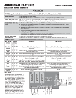
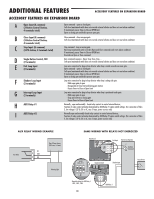
ADDITIONAL FEATURES ACCESSORY FEATURES ON CONTROL BOARD ACCESSORY FEATURES ON CONTROL BOARD A Open Input (& common) (3-Button Control Station, 4 terminals total) Open command - opens a closed gate. Hard open (maintained switch overrides external safeties and resets alarm condition) If maintained, pauses Timer-to-Close at OPEN limit. Opens a closing gate and holds open an open gate (within line-of-sight). B Close Input (& common) (3-Button Control Station, 4 terminals Close command - closes an open gate. Hard close (maintained switch overrides external safeties and resets alarm condition within line-of-sight) total) C Stop Input (& common) (3-Button Control Station, 4 terminals total) Stop command - stops a moving gate. Hard stop (maintained switch overrides Open and Close commands and resets alarm condition) If maintained, pauses Timer-to-Close at OPEN limit. Overrides Open and Close commands (within line-of-sight). D Fire Dept Open Input (2 terminals) Acts as hard open. Maintained input overrides (ignores) external safeties (photoelectric sensor and edge), pauses Timer-to-Close momentary input logic as single button control and safeties remain active, re-enables Timer-to-Close. E Exit Loop Input (2 terminals) Open command - opens a closed gate. Soft open (maintained switch does not override external safeties and does not reset alarm condition) If maintained, pauses Timer-to-Close at OPEN limit. Opens a closing gate and holds open an open gate. F Shadow Loop Input (2 terminals) Loop detector connection when loop is positioned under gate. - Holds open gate at open limit - Disregarded at CLOSE limit and during gate motion - Pauses Timer-to-Close at OPEN limit G CLOSE EYES/Interrupt Loop Input (2 terminals) CLOSE EYES/Interrupt Loop detector connection when loop is along the side of the gate. - Holds open gate at open limit - Stops and reverses a closing gate to open limit - Pauses Timer-to-Close at OPEN limit Close Direction Photoelectric Sensors, IR, or Infra-red detector wired to CLOSE EYES Input, disregarded during gate opening. Pulsed Photoelectric Sensors = monitored device putting out a pulse train when unblocked. Photoelectric Sensors, IR, Infra-red detector, contact opens fully with obstruction. H Close Edge (2 terminals) Close Direction Edge Sensor to Close Safety Input, disregarded during gate opening I Open Eyes/Edge (2 terminals) Open Direction Photoelectric Sensors, IR, Infra-red detector wired or Edge Sensor to Close Entrapments Input, disregarded during gate closing, Pulsed Photoelectric Sensors = monitored device putting out a pulse train when unblocked. Photoelectric Sensors, IR, Infra-red detector, edge sensor = normally open contact, contact reverses for 2 seconds with obstruction. J Comm Link (2 terminals) Commercial Link (two wires) - connects two operators together (primary-secondary wired connection) K Lock Outputs: Maglock (2 terminals, N.C. and COM) Relay contact output, Normally - closed (N.C.) output for maglocks Relay activates prior to motor activation and during motor run. Relay is off when motor is off. L Solenoid Lock & Common (2 terminals, N.O. and COM) Normally - open (N.O.) output for solenoid locks Relay activates prior to motor activation and during motor run. Relay is off when motor is off. M Accessory Power Out Switched, (2 terminals) 24 Vdc voltage out to power accessories, will turn off when gate is not in motion to save battery power Always on if Expansion Board is connected. N Accessory Power Out Un-switched, (2 terminals) 24 Vdc voltage out to power accessories, always ON 31
-
 1
1 -
2
-
3
-
4
-
5
-
6
-
7
-
8
-
9
-
10
-
11
-
12
-
13
-
14
-
15
-
16
-
17
-
18
-
19
-
20
-
21
-
22
-
23
-
24
-
25
-
26
-
27
-
 28
28 -
 29
29 -
 30
30 -
 31
31 -
 32
32 -
 33
33 -
 34
34 -
 35
35 -
 36
36 -
 37
37 -
 38
38 -
39
-
40
-
41
-
42
-
43
-
44
-
45
-
46
-
47
-
48
 |
 |