LiftMaster CSW24V CSW24V Installation Manual - Page 29
Finish Installation, Install The Cover
 |
View all LiftMaster CSW24V manuals
Add to My Manuals
Save this manual to your list of manuals |
Page 29 highlights
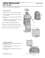
FINISH INSTALLATION INSTALL THE COVER INSTALL THE COVER The operator cover consists of two pieces: a rear cover and a front cover. The front cover can easily be removed to access the electrical box. To access the reset switch slide the access door up. The front cover and access door can be locked with the key. TO INSTALL THE COVER 1 Remove the operator arm from the output shaft by releasing the handle. 2 Align the tabs on the rear cover with the slots on the chassis and place the cover over the operator. 3 Secure both sides of the rear cover to the chassis with two 5/16-18 hex bolts and washers. 4 Reattach the operator arm to the output shaft (making sure the pin fits into the slot) and secure by pushing the handle down. 5 Place the operator arm cover over the operator arm and secure. 6 Align the front cover with the back cover, making sure the grooves line up. 7 Secure the front cover to the chassis with two 5/16-18 hex bolts and washers. 8 Secure the front cover to the rear cover using the 5/16-18 screw. 5/16-18 Hex Bolts and Washers Tabs on Rear Cover Slots on Chassis Groove on Front Cover 5/16-18 Screw Access Door TO LOCK THE ACCESS DOOR From the factory the access door for the reset switch will not be locked. To lock the access door follow the steps below: 1 Locate the lock tab on the back of the front cover and remove the screw securing the tab to the cover. 2 Turn the tab 180 degrees, then secure with the screw. The access door can now be locked. Lock Tab Access Door The basic installation is complete. Factory Default position 27 (back of front cover)
-
 1
1 -
2
-
3
-
4
-
5
-
6
-
7
-
8
-
9
-
10
-
11
-
12
-
13
-
14
-
15
-
16
-
17
-
18
-
19
-
20
-
21
-
22
-
23
-
 24
24 -
 25
25 -
 26
26 -
 27
27 -
 28
28 -
 29
29 -
 30
30 -
 31
31 -
 32
32 -
 33
33 -
 34
34 -
35
-
36
-
37
-
38
-
39
-
40
-
41
-
42
-
43
-
44
-
45
-
46
-
47
-
48
 |
 |
