LiftMaster CSW24V CSW24V Installation Manual - Page 17
Shorten The Operator Arm, Position The Gate Bracket
 |
View all LiftMaster CSW24V manuals
Add to My Manuals
Save this manual to your list of manuals |
Page 17 highlights
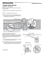
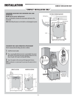
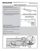
INSTALLATION COMPACT INSTALLATION ONLY SHORTEN THE OPERATOR ARM For a compact installation the operator arm will have to be shortened. 1 Take the operator arm apart and remove the inner sleeves from the outer tubing. 2 Cut the outer tubing of the operator arm sections to the lengths shown. 3 Put the arm back together and adjust the arm to the measurements as shown. Use the set screws on the arm to temporarily hold the arm in place while determining the correct measurements. 1 CUT 2 10" CUT 4" COMPACT INSTALLATION ONLY long arm section CUT 22" 4" short arm section 20" 3 POSITION THE GATE BRACKET NOTE: It may be necessary to attach horizontal reinforcement to the gate before attaching the gate bracket. Use the set screws on the arm to temporarily hold the arm in place while determining the correct measurements. 1 Position the operator arm onto the output shaft so that the pin slides into the slot. 2 Measure 33 inches from the gate hinge center. 3 Make sure the operator arm is level and tack weld the gate bracket in this position. Set Screws 23" 25-1/2" 2 33" Gate Hinge Center 1 Slot 3 Set Screws Tack weld 15 Output Shaft Pin
-
 1
1 -
2
-
3
-
4
-
5
-
6
-
7
-
8
-
9
-
10
-
11
-
 12
12 -
 13
13 -
 14
14 -
 15
15 -
 16
16 -
 17
17 -
 18
18 -
 19
19 -
 20
20 -
 21
21 -
 22
22 -
23
-
24
-
25
-
26
-
27
-
28
-
29
-
30
-
31
-
32
-
33
-
34
-
35
-
36
-
37
-
38
-
39
-
40
-
41
-
42
-
43
-
44
-
45
-
46
-
47
-
48
 |
 |
