LiftMaster CSL24ULWK Instructions - Page 4
Alignment, Test, Solid blue LED, indicates optimal alignment
 |
View all LiftMaster CSL24ULWK manuals
Add to My Manuals
Save this manual to your list of manuals |
Page 4 highlights
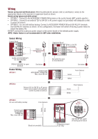
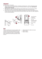
Alignment Reconnect power to the operator. 1. Align the sensor. The red LED indicates a misaligned or blocked sensor. The blue LED indicates signal strength. Slow blinking indicates weak signal. Fast blinking indicates stronger signal. Solid blue LED indicates optimal alignment. 2. When the sensor is optimally aligned, tighten the sensor bracket screws to secure the sensor in place (about 24in-lb of torque). For extra security, tighten with the set screw until it grips the sensor. 3. Place the wire cover onto the sensor bracket. Make sure the tabs on the wire cover slide into the slots on the top of the sensor bracket. Secure the wire cover with 8-32x3/8" screws. Wire cover is NOT intended for use with conduit installations. 1 2 Red LED indicates misaligned or blocked sensor Blue LED Solid blue indicates optimal alignment 3 Sensor bracket screw Set screw Test Test ALL installed sensors for proper operation. Place an obstruction in the sensor beam path and run the operator. The gate will stop and reverse. If the gate does not stop and reverse, refer to Troubleshooting below. Perform the test with the obstruction in three locations: • Halfway between the reflector and sensor • Near the sensor • Near the reflector
-
 1
1 -
 2
2 -
 3
3 -
 4
4 -
 5
5 -
 6
6 -
 7
7 -
 8
8 -
 9
9 -
 10
10 -
11
-
12
-
13
-
14
-
15
-
16
 |
 |
