LiftMaster CSL24ULWK Instructions - Page 2
Carton Inventory, Tools Needed, Installation, IMPORTANT
 |
View all LiftMaster CSL24ULWK manuals
Add to My Manuals
Save this manual to your list of manuals |
Page 2 highlights
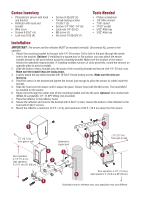
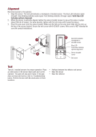
Carton Inventory • Photoelectric sensor with hood and bracket • Reflector with hood and bracket • Wire cover • Screws 8-32x1" (4) • Lock nuts 8-32 (4) • Screws 8-32x3/8" (2) • Thread-locking screws 10-32x1" (2) • Screws 1/4"-20x1-1/4" (6) • Lock nuts 1/4"-20 (2) • M3 screw (1) • Set screw 10-32x3/8" (1) Tools Needed • Philips screwdriver • 1/8" Allen wrench • 7/16" socket • 11/32" socket • 5/32" Allen key • 3/32" Allen key Installation IMPORTANT: The sensor and the reflector MUST be mounted vertically. Disconnect ALL power to the operator. 1. Attach the mounting bracket to the post with 1/4"-20 screws. Drill a hole in the post through the center hole in the bracket. Optional: If installing to a square post or flat surface, you may attach the sensor bracket directly to the post without using the mounting bracket. Make sure the location of the sensor follows the specified measurements. If installing multiple sensors in close proximity, mount the sensors on opposite sides to avoid crosstalk. 2. Slide the bottom sensor bracket onto the studs of the mounting bracket and secure with 1/4"-20 lock nuts. Make sure the bracket legs are facing down. 3. Loosely attach the top sensor bracket with 10-32x1" thread-locking screws. Make sure the slots are facing up. 4. Place the sensor in the bracket and tighten the screws just enough to allow the sensor to rotate inside the bracket. 5. Slide the hood over the sensor until it snaps into place. Secure hood with the M3 screw. The hood MUST be installed on the sensor. 6. Route wires through the center hole of the mounting bracket and into the post. Optional: Use conduit with NEMA 4X compatible 1/2"-14 NPT fitting (not provided). 7. Place the reflector in the reflector hood. 8. Secure the reflector and hood to the bracket with 8-32x1" screws. Secure the bottom of the reflector to the hood with 8-32x1" screws. 9. Mount the reflector a minimum of 3 ft. (.9 m) and maximum of 50 ft. (15.2 m) away from the sensor. 9 5 ≤ 5" (12.7 cm) from gate or wall Door operators: 4-1/2" (11.4 cm) Gate operators: 4" (10.2 cm)-26" (66 cm) Optional for square post 4 1 2 8 ≤ 5" (12.7 cm) from gate or wall 7 Door operators: 4-1/2" (11.4 cm) 6 Gate operators: 4" (10.2 cm)-26" (66 cm) 3 Illustrations are for reference only; your application may look different.
-
 1
1 -
 2
2 -
 3
3 -
 4
4 -
 5
5 -
 6
6 -
 7
7 -
 8
8 -
9
-
10
-
11
-
12
-
13
-
14
-
15
-
16
 |
 |
