LiftMaster CSL24ULWK Instructions - Page 3
Wiring, Sensor Wiring, Heater Wiring
 |
View all LiftMaster CSL24ULWK manuals
Add to My Manuals
Save this manual to your list of manuals |
Page 3 highlights
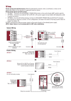
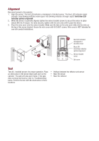
Wiring Sensor wiring (red and black wires): Wire the photoelectric sensors (red [+] and black [-] wires) to the appropriate inputs on the operator or expansion board as shown. Heater wiring (green and white wires): • OPTION 1 - Connect to the ACCESSORY POWER ON terminal on the control board (NOT polarity specific). • OPTION 2 - Connect to an external 12V to 24V DC or AC power supply (not provided) with adequate current to power all sensors. • OPTION 3 - For use with battery backup. Connect to ACCESSORY POWER ON and AUX RELAY terminals. Set AUX RELAY switches as shown. In this configuration, the heater will switch off during a power failure to extend the battery life. DO NOT overload the accessory power output on the control board or the external power supply. NOTE: Heater feature is not recommended for ANY solar installations. White Green White Green Sensor Wiring Control Board Black (-) Red (+) Expansion Board OR Red (+) to EYE or EYE/EDGE Black (-) to COM CLOSE EYES/INTERRUPT for close direction OR OPEN EYES/EDGE for open direction See below Heater Wiring OPTION 1 Control board ACCESSORY POWER ON Max. draw 500 mA Set switch for open or close direction See below Green From Sensors White OPTION 2 OR External 12V to 24V DC or AC power supply (not provided) with adequate current to power all sensors Green White From Sensors OPTION 3 For use with battery backup OR From Sensors Green White Control board ACCESSORY POWER ON Max. draw 500 mA Black (not provided) AUX RELAY will switch off during power failure Expansion board aux relay
-
 1
1 -
 2
2 -
 3
3 -
 4
4 -
 5
5 -
 6
6 -
 7
7 -
 8
8 -
 9
9 -
10
-
11
-
12
-
13
-
14
-
15
-
16
 |
 |
