LiftMaster CSL24ULWK Instructions
LiftMaster CSL24ULWK Manual
 |
View all LiftMaster CSL24ULWK manuals
Add to My Manuals
Save this manual to your list of manuals |
LiftMaster CSL24ULWK manual content summary:
- LiftMaster CSL24ULWK | Instructions - Page 1
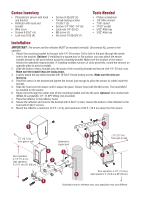
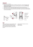
instructions. • Be sure to DISCONNECT ALL POWER to the operator BEFORE installing the photoelectric sensor. • The gate or door MUST be in the fully opened or closed position BEFORE installing the LiftMaster protection devices MUST be installed per the operator installation manual at each Entrapment - LiftMaster CSL24ULWK | Instructions - Page 2
rotate inside the bracket. 5. Slide the hood over the sensor until it snaps into place. Secure hood with the M3 screw. The hood MUST be installed on the sensor. 6. Route wires through the center hole of the mounting bracket and into the post. Optional: Use conduit with NEMA 4X compatible 1/2"-14 - LiftMaster CSL24ULWK | Instructions - Page 3
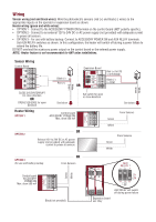
DO NOT overload the accessory power output on the control board or the external power supply. NOTE: Heater feature is not recommended for ANY solar installations. White Green White Green Sensor Wiring Control Board Black (-) Red (+) Expansion Board OR Red (+) to EYE or EYE/EDGE Black (-) to COM - LiftMaster CSL24ULWK | Instructions - Page 4
3 Sensor bracket screw Set screw Test Test ALL installed sensors for proper operation. Place an obstruction in the sensor beam path and run the operator. The gate will stop and reverse. If the gate does not stop and reverse, refer to Troubleshooting below. Perform the test with the obstruction in - LiftMaster CSL24ULWK | Instructions - Page 5
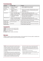
Troubleshooting , and hardware Warranty LiftMaster® warrants to the purchase. NOTICE: This device complies with Part 15 of the FCC rules and Industry installation. This equipment generates, uses and can radiate radio frequency energy and, if not installed and used in accordance with the instructions - LiftMaster CSL24ULWK | Instructions - Page 6
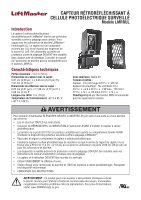
installer le dispositif de protection surveillé contre le piégeage LiftMaster®. • Raccorder et aligner correctement le capteur à cellule photoélectrique. • Installer de protection contre le piégeage DOIVENT être installés selon les instructions du manuel d'installation à chaque zone de piégeage. • Le - LiftMaster CSL24ULWK | Instructions - Page 7
le capteur jusqu'à ce qu'il s'encliquette en place. Fixer le capot avec la vis M3. Le capot DOIT être installé sur le capteur. 6. Acheminer les fils par le trou central du support de montage puis dans le poteau. En option : Se servir d'un conduit avec un raccord q/2 po-14 NPT (non - LiftMaster CSL24ULWK | Instructions - Page 8
alimentation accessoire sur la carte logique ou la source d'alimentation externe. REMARQUE : L'appareil de chauffage est déconseillé pour TOUTES les installations solaires. Blanc Vert Blanc Vert Câblage du capteur Carte logique Noir(-) Rouge (+) Carte d'extension OU Rouge (+) à EYE ou EYE/EDGE - LiftMaster CSL24ULWK | Instructions - Page 9
S'assurer que les pattes du couvre-fils glissent dans les fentes du dessus du support du capteur. Fixer le couvre-fils avec une vis 8-32x3/8 po. Le couvre-fils n'est PAS destiné à être utilisé avec des installations de conduites. Une DEL allumée en 2 rouge indique un 1 capteur désaligné ou obstru - LiftMaster CSL24ULWK | Instructions - Page 10
enfichable K41-39254: Réflecteur, support et quincaillerie Garantie LiftMaster® garantit à l'acheteur initial de ce installé et utilisé conformément aux instructions, peut causer un brouillage nuisible aux communications radio. Cependant, rien ne garantit l'absence de brouillage dans une installation - LiftMaster CSL24ULWK | Instructions - Page 11
/VCA Calentador: Controlado termostáticamente, NO recomendado para aplicaciones solares Para evitar posibles LESIONES GRAVES o la MUERTE cuando la LiftMaster®. • Conecte correctamente y alinee el sensor fotoeléctrico. • Instale el según las instrucciones del manual de instalación del operador - LiftMaster CSL24ULWK | Instructions - Page 12
. 7. Coloque el reflector en la campana del reflector. 8. Asegure el reflector y la campana a la ménsula con tornillos de 8-32 x 1 pulg . Asegure la parte inferior del reflector a la campana con tornillos de 8-32 x 1 pulg. 9. Monte el reflector a un mínimo de 3 pies (0.9 m) y un máximo de 50 pies (15 - LiftMaster CSL24ULWK | Instructions - Page 13
en el tablero de control o la fuente de alimentación externa. NOTA: La característica de calentador no es recomendable para NINGUNA instalación solar. Cableado del sensor Tablero de control Negro (-) Rojo (+) Tablero de expansión Rojo (+) para EYE o EYE/EDGE Negro (-) para COM O Blanco Verde - LiftMaster CSL24ULWK | Instructions - Page 14
en la ménsula del sensor. Asegúrese de que las lengüetas de la cubierta del cable se deslicen dentro de las ranuras en la parte superior de la ménsula del sensor. Asegure la cubierta del cable con tornillos de 8-32 x 3/8 pulg. La cubierta del cable NO está diseñada para - LiftMaster CSL24ULWK | Instructions - Page 15
enchufable K41-39254: Reflector, ménsula y herrajes Garantía LiftMaster® garantiza al primer comprador minorista de este producto que el mismo y cumple con los límites para un dispositivo digital de Clase B, conforme con la Parte 15 de las normas de la FCC y el estándar ICES de Industry Canada - LiftMaster CSL24ULWK | Instructions - Page 16
01-39358B © 2018, LiftMaster All Rights Reserved Tous droits réservés Todos los Derechos Reservados LiftMaster.com
-
 1
1 -
 2
2 -
 3
3 -
 4
4 -
 5
5 -
 6
6 -
 7
7 -
8
-
9
-
10
-
11
-
12
-
13
-
14
-
15
-
16
 |
 |

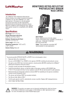
Introduction
The LiftMaster
®
Retro-Reflective Photoelectric
Sensor provides non-contact monitored entrapment
protection. For use with LiftMaster
®
UL Listed
gate operators. The sensor is a UL Recognized
Component and meets UL 325 requirements.
Monitored external entrapment protection devices
MUST be installed at each Entrapment Zone. Refer to
gate operator manual for compatibility with LMRRUL
sensor.
Specifications
Max Range:
50 ft. (15.2 m)
Sensor Dimensions with Hood:
2.29" W x 3.72" H x 2.76" D
Reflector Dimensions with Hood:
2.61" W x 4.72" H x 2" D
Cable Length
: 10 ft. (3 m)
Operating Temperature
: -40˚C to 65˚C
(-40˚F a 149˚F)
Outdoor Rating
: Nema 4X
Input voltage:
Sensor: Black/red wires 6.8 VDC, 20mA
Heater: Green/white wires 10-40VDC or 8-28 VAC, 2
watts max., 170mA @ 12 VDC/VAC,
85mA @ 24 VDC/VAC
Heater
: Thermostatically controlled, NOT
recommended for solar applications
MONITORED RETRO-REFLECTIVE
PHOTOELECTRIC SENSOR
Model LMRRUL
To prevent possible SERIOUS INJURY or DEATH from a closing gate or door:
•
Read and follow ALL instructions.
•
Be sure to DISCONNECT ALL POWER to the operator BEFORE installing the photoelectric sensor.
•
The gate or door MUST be in the fully opened or closed position BEFORE installing the LiftMaster
®
Monitored Entrapment Protection device.
•
Correctly connect and align the photoelectric sensor.
•
Install the photoelectric sensor so that the center of the sensor window is NO HIGHER than
4-1/2" (11.4 cm) above the floor for door operators and 26" (66 cm) above grade for gate operators.
•
Monitored external entrapment protection devices MUST be installed per the operator installation
manual at each Entrapment Zone.
•
The sensor and reflector MUST be mounted vertically.
•
Use the provided reflector ONLY.
•
Test the gate operator and ALL photoelectric sensors monthly. Replace ANY damaged devices.
•
SAVE THESE INSTRUCTIONS.
WARNING:
This product can expose you to chemicals including lead, which are known
to the State of California to cause cancer or birth defects or other reproductive harm.
For more information go to
www.P65Warnings.ca.gov.