LiftMaster CSL24UL Installation Manual
LiftMaster CSL24UL Manual
 |
View all LiftMaster CSL24UL manuals
Add to My Manuals
Save this manual to your list of manuals |
LiftMaster CSL24UL manual content summary:
- LiftMaster CSL24UL | Installation Manual - Page 1
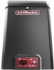
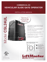
COMMERCIAL DC VEHICULAR SLIDE GATE OPERATOR INSTALLATION MANUAL Model CSL24UL LiftMaster 300 Windsor Drive Oak Brook, IL 60523 • THIS PRODUCT IS TO BE INSTALLED AND SERVICED BY A TRAINED GATE SYSTEMS TECHNICIAN ONLY. • This model is for use on vehicular passage gates ONLY and not intended for use - LiftMaster CSL24UL | Installation Manual - Page 2
Step 9 Install the Cover 22 ADJUSTMENT 23 Limit and Force Adjustment 23 Obstruction Test 24 PROGRAMMING 25 Remote Controls (Not Provided 25 LiftMaster Internet Gateway (not provided 26 Erase All Codes 26 Erase Limits 26 Constant Pressure Override (CPO 26 Gate Hold Open Feature - LiftMaster CSL24UL | Installation Manual - Page 3
slide gate operator will operate only after installation of a minimum of two independent* monitored entrapment protection devices in each direction; two in the open the gate is not moving. l KEEP GATES PROPERLY MAINTAINED. Read the owner's manual. Have a qualified service person make repairs to gate - LiftMaster CSL24UL | Installation Manual - Page 4
l Screen Mesh by a moving gate or barrier. l Vertical Posts l Instructional and Precautionary Signage 4. Install the gate operator only when: a. The operator is appropriate for the construction and the usage class of the gate. b. All openings of a horizontal slide gate are guarded or screened from - LiftMaster CSL24UL | Installation Manual - Page 5
fully open and fully closed positions. These stops shall be installed at either the top of the gate, or at the bottom of the gate where such gate will enter a receiver guide, refer to ASTM F2200 for panel types. The following provisions shall apply to Class IV vehicular horizontal slide gates - LiftMaster CSL24UL | Installation Manual - Page 6
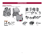
INTRODUCTION Carton Inventory NOT SHOWN: Documentation Packet, Chain #41 - 30 feet, Eye Bolt Kit 6 - LiftMaster CSL24UL | Installation Manual - Page 7
When Optional Transformer Kit Model 3PHCONV is installed in the field, operator is rated Solar Power Max 24 Vdc at 60 watts max. Maximum Gate Weight 1500 lbs. (680.4 kg) Minimum Gate Travel Distance 4 feet (1.2 m) Maximum Gate Travel Distance 50 feet (15.24 m) Maximum Gate 1 open entrapment - LiftMaster CSL24UL | Installation Manual - Page 8
and local building codes BEFORE installation. Conduit and Concrete Pad Trench and install conduit. Before trenching gate to stay open when vehicles are obstructing the gate path. Suggested for vehicles 14 feet (4.27 m) or longer. Vehicle loops are not required but are recommended. Before installing - LiftMaster CSL24UL | Installation Manual - Page 9
INSTALLATION l To AVOID damaging gas, power or other underground utility lines, l ALWAYS wear protective gloves and eye protection when digging more the battery or working around the battery compartment. than 18 inches (46 cm) deep. Types of Installations Standard Installation Rear Installation 9 - LiftMaster CSL24UL | Installation Manual - Page 10
codes before installation. Standard Installation 1. The gate operator should be installed near the front roller of the gate. Lay out the concrete pad. 2. Install Installation 1. The gate operator should be installed near the back of the gate in the OPEN position. Lay out the concrete pad. 2. Install - LiftMaster CSL24UL | Installation Manual - Page 11
Operator Attach the operator to the concrete pad with appropriate fasteners. The gate operator should be installed near the front roller of the gate or near the back of the gate (in the OPEN position). The space between the gate and the output sprocket must be a minimum of 4 inches (10.2 cm). NOTE - LiftMaster CSL24UL | Installation Manual - Page 12
Step 3 Attach the Chain Standard Installation DO NOT run the operator until instructed. 1. Manually open the gate and line up the front bracket so the chain will be level with the idler pulley and parallel to the ground. Weld the front bracket in this position. 2. Manually close the gate and line up - LiftMaster CSL24UL | Installation Manual - Page 13
instructed. NOTE: This installation will require two extra idler pulleys. Make sure all exposed pinch points are guarded. Refer to Gate Construction Information on page 4. 1. Move the back pulley to the bottom hole in the operator. 2. Manually close the gate and align the bottom bracket so the chain - LiftMaster CSL24UL | Installation Manual - Page 14
devices after completing installation of the operator. For testing instructions, refer to the manual provided with your entrapment protection device. Definitions ENTRAPMENT: The condition when a person is caught or held in a position that increases the risk of injury. SLIDE GATE ENTRAPMENT ZONE: An - LiftMaster CSL24UL | Installation Manual - Page 15
entrapment protection for the close direction. When an obstruction is sensed during gate closing the gate will open to the full open position and resets the Timer-to-Close. This input will be disregarded during gate opening. CLOSE EDGE (2 Terminals) The CLOSE EDGE input is for edge sensor entrapment - LiftMaster CSL24UL | Installation Manual - Page 16
single wire length. 1. Install the earth ground rod within of the remote controls will codes gate applications, power will have to be connected to each operator. Main power supply and control wiring MUST be run in separate conduits. SOLAR APPLICATIONS: For solar applications refer to Solar Panels - LiftMaster CSL24UL | Installation Manual - Page 17
INSTALLATION All control wiring used to connect external devices to Class 2 circuits of the operator must be (QPTZ) Power-Limited Circuit Cables, Type CL2, CL2P, CL2R, - LiftMaster CSL24UL | Installation Manual - Page 18
INSTALLATION AC power switch The AC Power switch on the operator will turn the incoming 120/240 Vac power ON or OFF. The operator's AC Power - LiftMaster CSL24UL | Installation Manual - Page 19
33AH battery The batteries are charged in the circuit by the integrated transformer. The batteries are for battery backup or solar installation. The 33AH application requires the Solar Harness Kit (Model K94-37236) and an additional battery tray (Model K10-34758-2). 1. Locate the J15 plug on the - LiftMaster CSL24UL | Installation Manual - Page 20
INSTALLATION Step 8 Dual gate setup There are two options for dual gate communication: wired or wireless. Follow the directions according to your application. Do not use wired and wireless communication simultaneously. Wired dual gate out of programming mode after 180 release the OPEN test button to - LiftMaster CSL24UL | Installation Manual - Page 21
INSTALLATION the control board. DUAL GATE WIRE TYPE (SHIELDED TWISTED PAIR CABLE) 22AWG up to 200 feet (61 m) 18AWG - 200-1000 feet (61-305 m) Wire must be will delay from the close limit when opening and be the first to close from the open limit. SLIDE GATE APPLICATIONS: Not applicable, set to OFF. - LiftMaster CSL24UL | Installation Manual - Page 22
Before installing the cover, follow the instructions in the Adjustment section to adjust the limits and force. The operator cover consists of two pieces: a rear cover and a front cover. The front cover can easily be removed to access the electrical box. To access the reset switch slide the access - LiftMaster CSL24UL | Installation Manual - Page 23
requires a 3-button remote control programmed to OPEN, CLOSE, and STOP. NOTE: The TEST buttons on the control board will not work until the limits have been set and the required entrapment protection devices are installed. Initial Limits and Force Adjustment For dual gate applications the limits - LiftMaster CSL24UL | Installation Manual - Page 24
injury to a person. The force setting is the same for both the open and close gate directions. 1. Open and close the gate with the TEST BUTTONS. 2. If the gate stops or reverses before reaching the fully open or closed position, increase the force by turning the force control slightly clockwise - LiftMaster CSL24UL | Installation Manual - Page 25
: OPTION Single button as OPEN only Single button (SBC) as OPEN, CLOSE, and STOP DESCRIPTION Program a single button on the remote control for open only. The Timer-to-Close can be set to close the gate. Program one remote control button as an open, close, and stop. PROGRAMMING STEPS 1. Press and - LiftMaster CSL24UL | Installation Manual - Page 26
Override is for use with KPW5 and KPW250 keypads (not provided). The KPW5/KPW250 wireless commercial keypads are security keypads and can only be programmed to ONE gate operator (see the KPW5/KPW250 manual for complete programming instructions). The Constant Pressure Override feature is intended to - LiftMaster CSL24UL | Installation Manual - Page 27
system is charging batteries (i.e. not running on batteries). Aux Relay Out - Tamper Attach alert signal (audible or (Slide Gates Only) visual alert system) to indicate if gate is manually tampered with by being pushed off of close limit. Attach alert signal (audible or visual alert system) to - LiftMaster CSL24UL | Installation Manual - Page 28
button is for programming remote controls and the network. 7 TIMER-TO-CLOSE dial: The TIMER-TO-CLOSE (TTC) dial can be set to automatically close the gate after a specified time period. The TTC is factory set to OFF. If the TTC is set to the OFF position, then the gate will remain open until the - LiftMaster CSL24UL | Installation Manual - Page 29
) Functionality Once the remote control has been programmed the operator will operate as follows: When gate is in the closed position, activation of the remote control button will open the gate. During the open cycle another activation of the remote control will stop the gate and the next activation - LiftMaster CSL24UL | Installation Manual - Page 30
exit probe, telephone entry, external exit loop detector, or any device that would command the gate to open. l Opens a closing gate and holds open an open gate, if maintained, pauses Timer-to-Close at OPEN limit. SHADOW (2 Terminals) This input is used for external shadow loop detector when loop is - LiftMaster CSL24UL | Installation Manual - Page 31
overrides external safeties and resets alarm condition). If maintained, pauses Timer-to-Close at OPEN limit. Opens a closing gate and holds open an open gate (within line-of-sight). l CLOSE and COM: Closes an open gate. Hard close (maintained switch overrides external safeties and resets alarm - LiftMaster CSL24UL | Installation Manual - Page 32
board overview 1. QUICK CLOSE switch: 6. EYE/EDGE switches: OFF: No change to the gate's normal operation. ON: When CLOSE EYES/Interrupt loop is deactivated it causes an opening or a stopped gate to close (ignores the Timer-to-Close). Set the EYE/EDGE switches as needed to obtain the desired - LiftMaster CSL24UL | Installation Manual - Page 33
when AC power or solar power is present. Energizes when on battery power. There is There is approximately a 10-12 second delay before approximately a 10-12 second delay before relay relay cutoff, after AC shutdown. cutoff, after AC shutdown. Energizes if gate is manually tampered with by being - LiftMaster CSL24UL | Installation Manual - Page 34
loop is inside secured area near gate. Open command - opens a closed gate. Soft open (maintained switch does not override external safeties and does not reset alarm condition) If maintained, pauses Timer-to-Close at OPEN limit. Opens a closing gate and holds open an open gate. 8 Shadow Loop Input - LiftMaster CSL24UL | Installation Manual - Page 35
MAINTAINED. Read the owner's manual. national and local electrical codes. NOTE: The operator should be on Have a qualified service person make repairs to gate hardware. a separate fused line of adequate capacity. l ALL maintenance MUST be performed by a LiftMaster professional. l NEVER let - LiftMaster CSL24UL | Installation Manual - Page 36
part 29-NP712 for replacement batteries. The batteries contain lead and need to be disposed of properly. The operator comes with two 7AH batteries. Two 33AH batteries (A12330SGLPK), with Solar Harness Kit (K94-37236) may be used in place of the 7AH batteries. Drive Train Over time, the drive chain - LiftMaster CSL24UL | Installation Manual - Page 37
TROUBLESHOOTING To protect against fire and electrocution: l DISCONNECT power (AC or solar and battery) BEFORE installing or servicing operator. For continued protection against fire: l Replace ONLY with fuse of same type and rating. Diagnostic Codes NOTE: When cycling or disconnecting power (ac/ - LiftMaster CSL24UL | Installation Manual - Page 38
TROUBLESHOOTING Diagnostic Codes Table Some codes are saved in the code history and some are not. If a code is not saved it will briefly appear on the display as it occurs, then disappear. LiftMaster System Installed System Informational External Entrapment Protection Inherent Entrapment - LiftMaster CSL24UL | Installation Manual - Page 39
TROUBLESHOOTING Code 69 70 71 72 73 74 75 80 81 82 83 84 91 93 99 Meaning Wireless edge triggered CLOSE EYE/INTERRUPT triggered, causing reversal, preventing close, or resetting TTC CLOSE EDGE triggered, causing reversal, NO preventing close, or canceling TTC OPEN are not supported. Make sure - LiftMaster CSL24UL | Installation Manual - Page 40
The timer is canceled blinks per second) OFF The gate is stopped ON The gate is opening or closing BATT LOW ACC PWR OVLD MEDIUM BLINK (1 Operator is in E1 (single blink per second) entrapment) FASTEST BLINK (8 The operator is in E2 (double blinks per second) entrapment) OFF No battery error - LiftMaster CSL24UL | Installation Manual - Page 41
active f. Vehicle loop detector or probe active g. Defective control board a. Gate does not move to a limit position b. Gate is too difficult to move c. Limits are set too close (slide gate applications only) Gate does not fully open or fully close when setting limits. Operator does not respond to - LiftMaster CSL24UL | Installation Manual - Page 42
TROUBLESHOOTING SYMPTOM Gate opens, but will not close with transmitter or Timer-to-Close. Gate closes, but will not open. Exit loop activation does not cause gate to open. Interrupt loop does not cause gate to stop and reverse. Shadow loop does not keep gate at open limit. Obstruction in gate solar - LiftMaster CSL24UL | Installation Manual - Page 43
TROUBLESHOOTING SYMPTOM Expansion board function not controlling gate. Maglock not solar panels b. Reduce the accessory power draw by using LiftMaster low power accessories c. Replace batteries d. Relocate the solar panels away from obstructions (trees, buildings, etc.) a. Add more solar panels - LiftMaster CSL24UL | Installation Manual - Page 44
batteries in the given zones as shown on the map below. Local geography and weather conditions may require additional solar panels. Solar powered gate operator installations are not supported in northern climates due to cold weather and a reduced number of hours of sunlight during the winter months - LiftMaster CSL24UL | Installation Manual - Page 45
APPENDIX Solar usage guide Typical System Standby Battery Current Consumption (mA) System voltage Main board with no radios programmed One or more LiftMaster® remote controls programmed MyQ® device or wireless dual gate programmed Expansion board Per loop detector LOOPDETLM (up to 3 loop detectors - LiftMaster CSL24UL | Installation Manual - Page 46
200 (61 m) 10 940 (286.5 m) 475 (144.8 m) 315 (96 m) Chart assumes: copper wire, 65°C, 5% drop, 30V nominal Installation Solar panel(s) MUST be installed facing south. Use a compass to determine direction. Below are general instructions for installing the solar panel(s). Your installation may - LiftMaster CSL24UL | Installation Manual - Page 47
Wire the Batteries Solar panel applications require the Solar Harness Kit model K94-37236, see Accessories. APPENDIX Wire the solar panels Proceed to the Dual Gate section (if applicable) or proceed to the Adjustment section. 47 - LiftMaster CSL24UL | Installation Manual - Page 48
Garage and Gate Monitor QUICK CLOSE Switch ON OFF ANTI-TAIL Switch ON OFF LOW BATT Switch Battery Fail OPEN: OPEN Battery Fail CLOSE: CLOSE Battery Fail OPEN: OPEN Battery Fail CLOSE: CLOSE AC FAIL OPEN/BATT OPEN Switch OPEN PRIMARY OPERATOR SECONDARY OPERATOR Program remote controls - LiftMaster CSL24UL | Installation Manual - Page 49
CLOSE button on the remote control again to set the close limit. 8. Cycle the gate open and close. This automatically sets the force. When limits are set properly the operator will automatically exit limit setting mode. Refer to the Adjustment section and follow the instructions for Fine Tune the - LiftMaster CSL24UL | Installation Manual - Page 50
WIRING DIAGRAM To protect against fire and electrocution: l DISCONNECT power (AC or solar and battery) BEFORE installing or servicing operator. For continued protection against fire: l Replace ONLY with fuse of same type and rating. 50 - LiftMaster CSL24UL | Installation Manual - Page 51
REPAIR PARTS 51 - LiftMaster CSL24UL | Installation Manual - Page 52
4-button, visor or key chain. The following remote controls are compatible with operators manufactured by LiftMaster after 1993. Contact your authorized LiftMaster dealer for additional details and options. 3-button remote control The 3-button remote control can be programmed to control the operator - LiftMaster CSL24UL | Installation Manual - Page 53
plate For post-mounting models CSL24UL, CSW24UL CSW200UL and SL3000UL commercial gate operators. Posts not included. Model MPEL Remote antenna extension kit The remote antenna extension kit allows the antenna to be remotely installed. Model 86LM LiftMaster® internet gateway Internet enabled - LiftMaster CSL24UL | Installation Manual - Page 54
this product. Then send this product, pre-paid and insured, to our service center for warranty repair. You will be advised of shipping instructions when you call. Please include a brief description of the problem and a dated proof-of-purchase receipt with any product returned for warranty repair - LiftMaster CSL24UL | Installation Manual - Page 55
NOTES 55 - LiftMaster CSL24UL | Installation Manual - Page 56
300 Windsor Drive Oak Brook, IL 60523 LiftMaster.com © 2018, The Chamberlain Group, Inc. - All Rights Reserved 01-39381B
-
 1
1 -
 2
2 -
 3
3 -
 4
4 -
 5
5 -
 6
6 -
 7
7 -
8
-
9
-
10
-
11
-
12
-
13
-
14
-
15
-
16
-
17
-
18
-
19
-
20
-
21
-
22
-
23
-
24
-
25
-
26
-
27
-
28
-
29
-
30
-
31
-
32
-
33
-
34
-
35
-
36
-
37
-
38
-
39
-
40
-
41
-
42
-
43
-
44
-
45
-
46
-
47
-
48
-
49
-
50
-
51
-
52
-
53
-
54
-
55
-
56
 |
 |
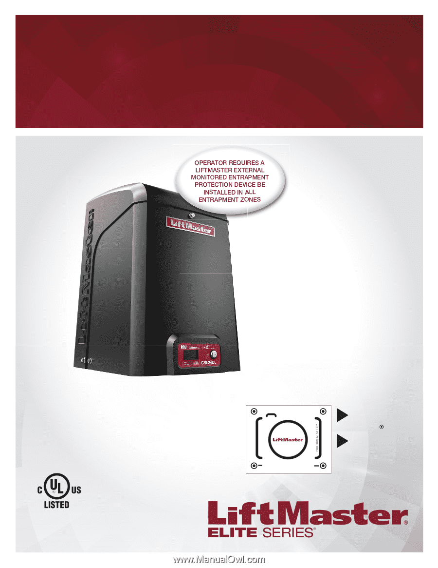
COMMERCIAL DC
VEHICULAR SLIDE GATE OPERATOR
INSTALLATION MANUAL
•
THIS PRODUCT IS TO BE INSTALLED AND
SERVICED BY A TRAINED GATE SYSTEMS
TECHNICIAN ONLY.
•
This model is for use on vehicular passage
gates ONLY and not intended for use on
pedestrian passage gates.
•
This model is intended for use in Class I, II, III
and IV vehicular slide gate applications.
•
Visit LiftMaster.com to locate a professional
installing dealer in your area.
•
This gate operator is compatible with MyQ
®
and Security+ 2.0
®
accessories.
LiftMaster
300 Windsor Drive
Oak Brook, IL 60523
Access installation and technical support
guides or register this product
Send it in
by texting the
photo to 71403.
Take a photo
of the
camera icon including
the points (
).
1.
2.
Model
CSL24UL
•
•
•
•
•
CSL24ULTECH