Lenovo ThinkServer TS440 (English) User Guide - Page 47
Connecting the cables, Connecting the mini-SAS signal cable from the system board to the backplane
 |
View all Lenovo ThinkServer TS440 manuals
Add to My Manuals
Save this manual to your list of manuals |
Page 47 highlights
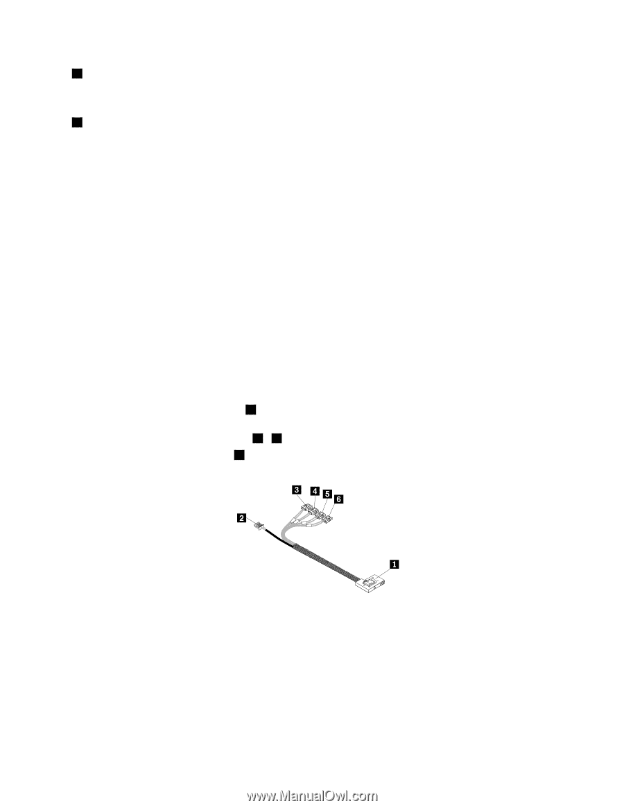
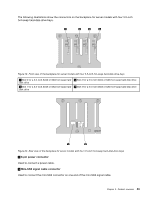
2 Mini-SAS signal cable connector 1 Used to connect the mini-SAS connector on one end of the mini-SAS signal cable. 3 Mini-SAS signal cable connector 0 Used to connect the mini-SAS connector on one end of the mini-SAS signal cable. Connecting the cables This topic provides instructions on the following cable connections: • "Connecting the mini-SAS signal cable from the system board to the backplane for server models with hot-swap hard disk drives" on page 35. • "Connecting the mini-SAS signal cables from the RAID card to the backplanes for server models with hot-swap hard disk drives" on page 36. • "Connecting the SATA signal cables from the system board to the non-hot-swap hard disk drives" on page 38. Connecting the mini-SAS signal cable from the system board to the backplane for server models with hot-swap hard disk drives For server models with up to four 3.5-inch SATA hot-swap hard disk drives installed, you can use the mini-SAS signal cable that has four SATA connectors and one Serial General Purpose Input/Output (SGPIO) connector for cable connection. To connect the mini-SAS signal cable from the system board to the backplane, do the following: 1. Connect the mini-SAS connector 1 to the mini-SAS signal cable connector 0 on the backplane. The backplane is installed on the lower hard-disk-drive cage. 2. Connect the four SATA connectors 3 - 6 to the SATA connectors 0-3 on the system board. 3. Connect the SGPIO connector 2 to the SATA SGPIO connector on the system board. Figure 23. Mini-SAS signal cable with four SATA connectors and one SATA SGPIO connector To connect the power cable from the system board to the backplane, connect the 4-pin power connector on one end of the power cable to the 4-pin power connector on the system board. Then, connect the other power connector on the other end of the power cable to the power connector on the backplane. Chapter 3. Product overview 35
-
 1
1 -
2
-
3
-
4
-
5
-
6
-
7
-
8
-
9
-
10
-
11
-
12
-
13
-
14
-
15
-
16
-
17
-
18
-
19
-
20
-
21
-
22
-
23
-
24
-
25
-
26
-
27
-
28
-
29
-
30
-
31
-
32
-
33
-
34
-
35
-
36
-
37
-
38
-
39
-
40
-
41
-
 42
42 -
 43
43 -
 44
44 -
 45
45 -
 46
46 -
 47
47 -
 48
48 -
 49
49 -
 50
50 -
 51
51 -
 52
52 -
53
-
54
-
55
-
56
-
57
-
58
-
59
-
60
-
61
-
62
-
63
-
64
-
65
-
66
-
67
-
68
-
69
-
70
-
71
-
72
-
73
-
74
-
75
-
76
-
77
-
78
-
79
-
80
-
81
-
82
-
83
-
84
-
85
-
86
-
87
-
88
-
89
-
90
-
91
-
92
-
93
-
94
-
95
-
96
-
97
-
98
-
99
-
100
-
101
-
102
-
103
-
104
-
105
-
106
-
107
-
108
-
109
-
110
-
111
-
112
-
113
-
114
-
115
-
116
-
117
-
118
-
119
-
120
-
121
-
122
-
123
-
124
-
125
-
126
-
127
-
128
-
129
-
130
-
131
-
132
-
133
-
134
-
135
-
136
-
137
-
138
-
139
-
140
-
141
-
142
-
143
-
144
-
145
-
146
-
147
-
148
-
149
-
150
-
151
-
152
-
153
-
154
-
155
-
156
-
157
-
158
-
159
-
160
-
161
-
162
-
163
-
164
-
165
-
166
-
167
-
168
-
169
-
170
-
171
-
172
-
173
-
174
-
175
-
176
-
177
-
178
-
179
-
180
-
181
-
182
-
183
-
184
-
185
-
186
-
187
-
188
-
189
-
190
-
191
-
192
-
193
-
194
-
195
-
196
 |
 |