Lenovo ThinkServer TS440 (English) User Guide - Page 156
Replacing the front system fan 1
 |
View all Lenovo ThinkServer TS440 manuals
Add to My Manuals
Save this manual to your list of manuals |
Page 156 highlights
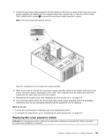
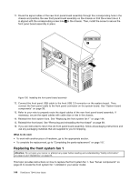
11. Route the signal cables of the new front panel board assembly through the corresponding hole in the chassis and position the new front panel board assembly on the chassis so that the screw hole in it is aligned with the corresponding screw hole 1 in the chassis. Then, install the screw to secure the front panel board assembly in place. Figure 100. Installing the front panel board assembly 12. Connect the front panel USB cable to the front USB 3.0 connector on the system board. Then, connect the front panel cable to the front panel connector on the system board. See "System board components" on page 38. 13. Refer to your note to properly route the signal cables of the new front panel board assembly. If necessary, secure the signal cables with cable clips or ties in the chassis. 14. Reinstall the front system fans. See "Replacing the front system fan 1" on page 144. 15. Reinstall the front bezel. See "Removing and reinstalling the front bezel" on page 69. 16. If you are instructed to return the old front panel board assembly, follow all packaging instructions and use any packaging materials that are supplied to you for shipping. What to do next: • To work with another piece of hardware, go to the appropriate section. • To complete the replacement, go to "Completing the parts replacement" on page 157. Replacing the front system fan 1 Attention: Do not open your server or attempt any repair before reading and understanding "Safety information" on page iii and "Guidelines" on page 65. This topic provides instructions on how to replace the front system fan 1. See "Server components" on page 23 to locate the front system fan 1 installed in your server model. 144 ThinkServer TS440 User Guide
-
 1
1 -
2
-
3
-
4
-
5
-
6
-
7
-
8
-
9
-
10
-
11
-
12
-
13
-
14
-
15
-
16
-
17
-
18
-
19
-
20
-
21
-
22
-
23
-
24
-
25
-
26
-
27
-
28
-
29
-
30
-
31
-
32
-
33
-
34
-
35
-
36
-
37
-
38
-
39
-
40
-
41
-
42
-
43
-
44
-
45
-
46
-
47
-
48
-
49
-
50
-
51
-
52
-
53
-
54
-
55
-
56
-
57
-
58
-
59
-
60
-
61
-
62
-
63
-
64
-
65
-
66
-
67
-
68
-
69
-
70
-
71
-
72
-
73
-
74
-
75
-
76
-
77
-
78
-
79
-
80
-
81
-
82
-
83
-
84
-
85
-
86
-
87
-
88
-
89
-
90
-
91
-
92
-
93
-
94
-
95
-
96
-
97
-
98
-
99
-
100
-
101
-
102
-
103
-
104
-
105
-
106
-
107
-
108
-
109
-
110
-
111
-
112
-
113
-
114
-
115
-
116
-
117
-
118
-
119
-
120
-
121
-
122
-
123
-
124
-
125
-
126
-
127
-
128
-
129
-
130
-
131
-
132
-
133
-
134
-
135
-
136
-
137
-
138
-
139
-
140
-
141
-
142
-
143
-
144
-
145
-
146
-
147
-
148
-
149
-
150
-
 151
151 -
 152
152 -
 153
153 -
 154
154 -
 155
155 -
 156
156 -
 157
157 -
 158
158 -
 159
159 -
 160
160 -
 161
161 -
162
-
163
-
164
-
165
-
166
-
167
-
168
-
169
-
170
-
171
-
172
-
173
-
174
-
175
-
176
-
177
-
178
-
179
-
180
-
181
-
182
-
183
-
184
-
185
-
186
-
187
-
188
-
189
-
190
-
191
-
192
-
193
-
194
-
195
-
196
 |
 |
