HP EliteOne 700 Maintenance & Service Guide - Page 60
WLAN modules are designed with a notch to prevent incorrect insertion.
 |
View all HP EliteOne 700 manuals
Add to My Manuals
Save this manual to your list of manuals |
Page 60 highlights
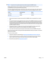
5. Lift the module to a 45-degree angle, and then pull it away to remove it from the socket (3). To install the WLAN module, reverse the removal procedures. When connecting the antennas cables, connect the cable labeled "1" to the MAIN connector on the module and the cable labeled "2" to the AUX connector on the module. NOTE: WLAN modules are designed with a notch to prevent incorrect insertion. 50 Chapter 5 Removal and Replacement Procedures ENWW
-
 1
1 -
2
-
3
-
4
-
5
-
6
-
7
-
8
-
9
-
10
-
11
-
12
-
13
-
14
-
15
-
16
-
17
-
18
-
19
-
20
-
21
-
22
-
23
-
24
-
25
-
26
-
27
-
28
-
29
-
30
-
31
-
32
-
33
-
34
-
35
-
36
-
37
-
38
-
39
-
40
-
41
-
42
-
43
-
44
-
45
-
46
-
47
-
48
-
49
-
50
-
51
-
52
-
53
-
54
-
 55
55 -
 56
56 -
 57
57 -
 58
58 -
 59
59 -
 60
60 -
 61
61 -
 62
62 -
 63
63 -
 64
64 -
 65
65 -
66
-
67
-
68
-
69
-
70
-
71
-
72
-
73
-
74
-
75
-
76
-
77
-
78
-
79
-
80
-
81
-
82
-
83
-
84
-
85
-
86
-
87
-
88
-
89
-
90
-
91
-
92
-
93
-
94
-
95
-
96
-
97
-
98
-
99
-
100
-
101
-
102
-
103
-
104
-
105
-
106
-
107
-
108
-
109
-
110
-
111
-
112
-
113
-
114
-
115
-
116
-
117
-
118
-
119
-
120
-
121
-
122
-
123
-
124
-
125
-
126
-
127
-
128
-
129
-
130
-
131
-
132
-
133
-
134
-
135
-
136
-
137
-
138
-
139
-
140
-
141
-
142
-
143
-
144
-
145
-
146
-
147
-
148
-
149
-
150
-
151
-
152
-
153
-
154
-
155
-
156
-
157
-
158
-
159
-
160
-
161
-
162
-
163
-
164
-
165
-
166
-
167
-
168
-
169
-
170
-
171
-
172
-
173
-
174
-
175
-
176
-
177
-
178
-
179
-
180
-
181
-
182
-
183
-
184
-
185
-
186
-
187
-
188
-
189
-
190
-
191
-
192
-
193
-
194
 |
 |

5.
Lift the module to a 45-degree angle, and then pull it away to remove it from the socket
(3)
.
To install the WLAN module, reverse the removal procedures.
When connecting the antennas cables, connect the cable labeled “1” to the MAIN connector on the module
and the cable labeled “2” to the AUX connector on the module.
NOTE:
WLAN modules are designed with a notch to prevent incorrect insertion.
50
Chapter 5
Removal and Replacement Procedures
ENWW