Epson H5200 Service Manual - Page 96
Paper Take-Up Roller Removal, Removing the Paper Take-Up Assembly
 |
View all Epson H5200 manuals
Add to My Manuals
Save this manual to your list of manuals |
Page 96 highlights
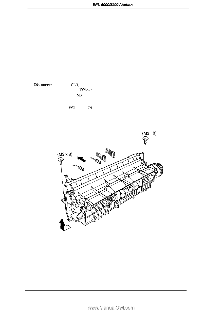
Disassembly and Assembly EPL-5000/5200/Action Laser 1000/1500 Service Manual 3.2.3.12 Paper Take-Up Roller Removal 1. Open the top cover. Remove the imaging cartridge. Cover the imaging cartridge to protect it from the light or place it in a dark area. 2. Remove the control panel. (Refer to Section 3.2.1.3.) 3. Remove the paper cover, 4. Remove the left and right covers. (Refer to Section 3.2.2.1.) 5. Remove the top cover. (Refer to Section 3.2.2.1.) 6. Remove the rear frame. (Refer to Section 3.2.2.2.) 7. Remove the fusing unit. (Refer to Section 3.2.3.9.) 8. Remove the power supply unit. (Refer to Section 3.2.3.2.) 9. Remove the printhead unit. (Refer to Section 3.2.3.4.) 10. Remove the image transfer assembly. (Refer to Section 3.2.3 .11.) 11. Discomect comectors CN1, CN3, the red wire terminal, and the black wire terminal on the high voltage supply board (PW13-F). 12. Remove the 2 CC screws (M3 x 8) on the guide plate. 13. Remove the guide plate and the paper empty sensor flag. 14. Remove 2 CC screws (M3 x 8) on the paper take-up assembly. 15. Slide the paper-take up assembly to the right, lift the left side up, and remove the paper take-up assembly. CC (M3 X 8) cc Figure 3-23. Removing the Paper Take-Up Assembly 3-18 Rev. A
-
 1
1 -
2
-
3
-
4
-
5
-
6
-
7
-
8
-
9
-
10
-
11
-
12
-
13
-
14
-
15
-
16
-
17
-
18
-
19
-
20
-
21
-
22
-
23
-
24
-
25
-
26
-
27
-
28
-
29
-
30
-
31
-
32
-
33
-
34
-
35
-
36
-
37
-
38
-
39
-
40
-
41
-
42
-
43
-
44
-
45
-
46
-
47
-
48
-
49
-
50
-
51
-
52
-
53
-
54
-
55
-
56
-
57
-
58
-
59
-
60
-
61
-
62
-
63
-
64
-
65
-
66
-
67
-
68
-
69
-
70
-
71
-
72
-
73
-
74
-
75
-
76
-
77
-
78
-
79
-
80
-
81
-
82
-
83
-
84
-
85
-
86
-
87
-
88
-
89
-
90
-
 91
91 -
 92
92 -
 93
93 -
 94
94 -
 95
95 -
 96
96 -
 97
97 -
 98
98 -
 99
99 -
 100
100 -
 101
101 -
102
-
103
-
104
-
105
-
106
-
107
-
108
-
109
-
110
-
111
-
112
-
113
-
114
-
115
-
116
-
117
-
118
-
119
-
120
-
121
-
122
-
123
-
124
-
125
-
126
-
127
-
128
-
129
-
130
-
131
-
132
-
133
-
134
-
135
-
136
-
137
-
138
-
139
-
140
-
141
-
142
-
143
-
144
-
145
-
146
-
147
-
148
-
149
-
150
-
151
-
152
-
153
-
154
-
155
-
156
 |
 |