Epson H5200 Service Manual - Page 130
A.1.2 Engine Controller Board PWB-A Board, Table A-8., Pin Assignment, Deectiption
 |
View all Epson H5200 manuals
Add to My Manuals
Save this manual to your list of manuals |
Page 130 highlights
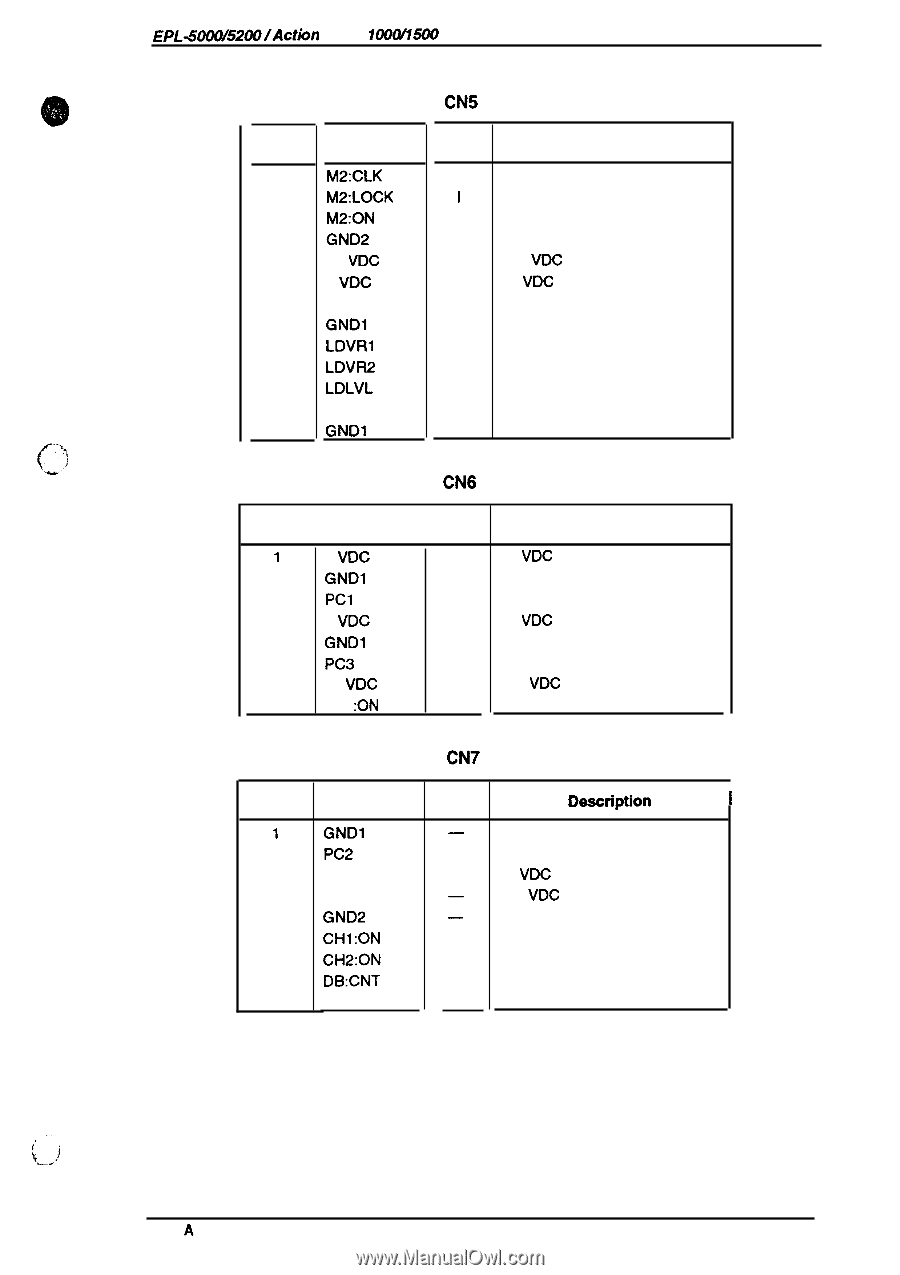
EPL-500W52001Action Lacer 100W151M Service Manual A.1.2 Engine Controller Board (PWB-A Board) Table A-8. CN5 Pin Assignment Pin No. Signal Name I/o Description 1 M2:CLK 2 M2:LOCK 3 M2:ON 4 GND2 5 24 VDC 6 5 VDC 7 LDATA 8 GND1 9 LDVR1 10 LDVR2 11 LDLVL 12 SSCAN 13 GND1 o M2 drive clock I M2 look signal o M2 drive - Ground - +24 VDC - +5 VDC o Laser data - Ground o Laser power adjust 1 0 Laser power adjust 2 I Laser power signal I Horizontal synchronous signal - Ground Table A-9. CN6 Pin Assignment Pin No. 1 2 3 4 5 6 7 8 Signal Name l/O 5 VDC - GND1 - Pcl I 5 VDC - GND1 - PC3 I 24 VDC - SL1 :ON o Description +5 VDC Ground Paper empty +5 VDC Ground Paper exit +24 VDC Paper take-up solenoid drive Table A-10. CN7 Pin Assignment Pin No. Signal Name I/o Deectiption 1 GND1 2 PC2 3 DC5V 4 DC24V 5 GND2 6 CH1 :ON 7 CH2:ON 8 DB:CNT 9 M3:CNT - Ground I Paper take-up +5 VDC - +24 VDC - Ground o Drum charge on 0 Image transfer on 0 Developing bias control 0 M3 control Appendix , ,., \_w! Rev. A A-9
-
 1
1 -
2
-
3
-
4
-
5
-
6
-
7
-
8
-
9
-
10
-
11
-
12
-
13
-
14
-
15
-
16
-
17
-
18
-
19
-
20
-
21
-
22
-
23
-
24
-
25
-
26
-
27
-
28
-
29
-
30
-
31
-
32
-
33
-
34
-
35
-
36
-
37
-
38
-
39
-
40
-
41
-
42
-
43
-
44
-
45
-
46
-
47
-
48
-
49
-
50
-
51
-
52
-
53
-
54
-
55
-
56
-
57
-
58
-
59
-
60
-
61
-
62
-
63
-
64
-
65
-
66
-
67
-
68
-
69
-
70
-
71
-
72
-
73
-
74
-
75
-
76
-
77
-
78
-
79
-
80
-
81
-
82
-
83
-
84
-
85
-
86
-
87
-
88
-
89
-
90
-
91
-
92
-
93
-
94
-
95
-
96
-
97
-
98
-
99
-
100
-
101
-
102
-
103
-
104
-
105
-
106
-
107
-
108
-
109
-
110
-
111
-
112
-
113
-
114
-
115
-
116
-
117
-
118
-
119
-
120
-
121
-
122
-
123
-
124
-
 125
125 -
 126
126 -
 127
127 -
 128
128 -
 129
129 -
 130
130 -
 131
131 -
 132
132 -
 133
133 -
 134
134 -
 135
135 -
136
-
137
-
138
-
139
-
140
-
141
-
142
-
143
-
144
-
145
-
146
-
147
-
148
-
149
-
150
-
151
-
152
-
153
-
154
-
155
-
156
 |
 |