Dell Latitude 5300 Service Manual
Dell Latitude 5300 Manual
 |
View all Dell Latitude 5300 manuals
Add to My Manuals
Save this manual to your list of manuals |
Dell Latitude 5300 manual content summary:
- Dell Latitude 5300 | Service Manual - Page 1
Dell Latitude 5300 Service Manual 1 Regulatory Model: P97G Regulatory Type: P97G001 June 2020 Rev. A02 - Dell Latitude 5300 | Service Manual - Page 2
data and tells you how to avoid the problem. WARNING: A WARNING indicates a potential for property damage, personal injury, or death. © 2019 -2020 Dell Inc. or its subsidiaries. All rights reserved. Dell, EMC, and other trademarks are trademarks of Dell Inc. or its subsidiaries. Other trademarks may - Dell Latitude 5300 | Service Manual - Page 3
data and tells you how to avoid the problem. WARNING: A WARNING indicates a potential for property damage, personal injury, or death. © 2019 -2020 Dell Inc. or its subsidiaries. All rights reserved. Dell, EMC, and other trademarks are trademarks of Dell Inc. or its subsidiaries. Other trademarks may - Dell Latitude 5300 | Service Manual - Page 4
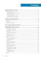
Contents Chapter 1: Working on your computer 7 Safety instructions...7 Before working inside your computer...7 Safety precautions...8 Electrostatic discharge-ESD protection...8 ESD field service kit ...9 Transporting sensitive components...10 After working inside your computer...10 Chapter 2: - Dell Latitude 5300 | Service Manual - Page 5
Removing the speakers...43 Installing the speakers...46 System fan...49 Removing the system fan...49 Installing the system fan...51 Heat sink...53 ...53 ...54 DC-in port...55 Removing the DC-in port...55 Installing the DC-in port...57 LED board...59 Removing the LED board...59 Installing the LED - Dell Latitude 5300 | Service Manual - Page 6
...116 Replacing the display back cover...116 Palmrest assembly...117 Replacing the palmrest and keyboard assembly 117 Chapter 5: Troubleshooting...120 Dell SupportAssist Pre-boot System Performance Check diagnostics 120 Running the SupportAssist Pre-Boot System Performance Check 120 System - Dell Latitude 5300 | Service Manual - Page 7
only perform troubleshooting and simple repairs as authorized in your product documentation, or as directed by the online or telephone service and support team. Damage due to servicing that is not authorized by Dell is not covered by your warranty. Read and follow the safety instructions that came - Dell Latitude 5300 | Service Manual - Page 8
any disassembly instructions. Observe the of getting electrocuted. Standby power Dell products with standby power must be is done through the use of a field service electrostatic discharge (ESD) kit. When connecting a not be obvious, such as intermittent problems or a shortened product life span - Dell Latitude 5300 | Service Manual - Page 9
of damage to recognize and troubleshoot is the intermittent (also ESD mat, and the hardware is known as bonding. Use only Field Service kits with a wrist strap, mat, and bonding wire. Never use wireless parts or parts to be returned to Dell, it is critical to place these parts in anti-static bags - Dell Latitude 5300 | Service Manual - Page 10
servicing Dell products. In addition, it is critical that technicians keep sensitive parts separate from all insulator parts while performing service base, and point your toes out. 2. Tighten stomach muscles. Abdominal muscles support your spine when you lift, offsetting the force of the load. 3. - Dell Latitude 5300 | Service Manual - Page 11
between host computers and peripheral devices like mice, keyboards, external drivers, and printers. Table 1. USB evolution Type Data Transfer devices ● New power management features ● Full-duplex data transfers and support for new transfer types ● Backward USB 2.0 compatibility ● New connectors - Dell Latitude 5300 | Service Manual - Page 12
3.1 Gen 1 products: ● External Desktop USB 3.0/USB 3.1 Gen 1 Hard Drives ● Portable USB 3.0/USB 3.1 Gen 1 Hard Drives ● USB 3.0/USB 3.1 Gen 1 Drive Docks & Adapters ● USB 3.0/USB 3.1 Gen 1 Flash Drives & Readers ● USB 3.0/USB 3.1 Gen 1 Solid-state Drives ● USB 3.0/USB 3.1 Gen 1 RAIDs ● Optical Media - Dell Latitude 5300 | Service Manual - Page 13
connected to a power cable, and that external display would charge your laptop as you used it as an external display - all via the one little USB Type-C connection. To use this, the device and the cable have to support USB Power Delivery. Just having a USB Type-C connection doesn't necessarily mean - Dell Latitude 5300 | Service Manual - Page 14
that does it all delivering the fastest, most versatile connection to any dock, display or data device like an external hard drive. Thunderbolt 3 uses a USB Type-C connector/port to connect to supported peripherals. 1. Thunderbolt 3 uses USB Type-C connector and cables - It is compact and reversible - Dell Latitude 5300 | Service Manual - Page 15
and confusion of multiple cables currently used in A/V systems. ● HDMI supports communication between the video source (such as a DVD player) and the DTV, enabling new functionality. Power button LED behavior On certain Dell Latitude systems, the power button LED is used to provide an indication of - Dell Latitude 5300 | Service Manual - Page 16
Power button with fingerprint reader will have no LED and will leverage the available LED's in the system to provide indication of the system status ● Power Adapter LED: ○ The LED on Power adapter connector illuminates white when power is supplied from electrical outlet. ● Battery Indicator LED: - Dell Latitude 5300 | Service Manual - Page 17
3 Major components of your system 1. Base cover 3. Heatsink 2. DC-in port 4. Memory modules Major components of your system 17 - Dell Latitude 5300 | Service Manual - Page 18
fan 6. Solid state drive 8. Speakers 10. Palmrest assembly 12. Touchpad button board 14. Coin-cell battery 16. WWAN card 18. NOTE: Dell provides a list of components and their part numbers for the original system configuration purchased. These parts are available according to warranty coverages - Dell Latitude 5300 | Service Manual - Page 19
4 Disassembly and reassembly NOTE: The images in this document may differ from your computer depending on the configuration you ordered. Topics: • MicroSD card • SIM card tray • Base cover • Battery • WWAN card • WLAN card • Memory modules • Solid-state drive • Speakers • System fan • Heat sink • DC - Dell Latitude 5300 | Service Manual - Page 20
Installing the microSD card Steps 1. Align the microSD card to its slot on the computer [1]. 2. Slide the microSD card into the slot until it clicks into place [2]. 20 Disassembly and reassembly - Dell Latitude 5300 | Service Manual - Page 21
Next steps Follow the procedures in After working inside your computer. SIM card tray Removing the SIM card tray Prerequisites Follow the procedure in Before working inside your computer Steps 1. Insert a pin into the hole of the SIM card tray and push inward until the tray is released [1, 2]. 2. - Dell Latitude 5300 | Service Manual - Page 22
Installing the SIM card tray Steps 1. Place the SIM card into the SIM card tray with the metallic contact facing up [1]. 2. Align the SIM card tray with the slot on the computer and carefully slide it in [2]. 3. Slide the SIM card tray into the slot, until it clicks into place [3]. 22 Disassembly - Dell Latitude 5300 | Service Manual - Page 23
Next steps Follow the procedures in After working inside your computer Base cover Removing the base cover Prerequisites 1. Follow the procedure in before working inside your computer. 2. Remove the microSD card. Steps 1. Loosen the eight captive screws that secure the base cover to the computer. - Dell Latitude 5300 | Service Manual - Page 24
2. Using a plastic scribe [1], pry the base cover from the top-left corner and continue to work on the sides to open the base cover [2]. 24 Disassembly and reassembly - Dell Latitude 5300 | Service Manual - Page 25
3. Lift and remove the base cover away from the computer. Disassembly and reassembly 25 - Dell Latitude 5300 | Service Manual - Page 26
4. After removing the base cover, remove the SIM cover. To remove the SIM cover pry the dummy SIM card upwards from the recess point which is the area between the dummy SIM card and system chassis. Installing the base cover Steps 1. Transfer the SIM cover to the new base cover. 2. Align and place - Dell Latitude 5300 | Service Manual - Page 27
3. Press the edges and sides of the base cover until it snaps into place. Disassembly and reassembly 27 - Dell Latitude 5300 | Service Manual - Page 28
4. Tighten the eight captive screws to secure the base cover to the computer. 28 Disassembly and reassembly - Dell Latitude 5300 | Service Manual - Page 29
any kind to pry on or against the battery. ● Ensure any screws during the servicing of this product are not lost or misplaced, to prevent accidental puncture or damage to such an instance, contact Dell technical support for assistance. See www.dell.com/contactdell. Disassembly and reassembly 29 - Dell Latitude 5300 | Service Manual - Page 30
● Always purchase genuine batteries from www.dell.com or authorized Dell partners and resellers. Removing the battery Prerequisites 1. Follow the procedure in before working inside your computer. 2. Remove the microSD card. 3. Remove the base cover. Steps 1. - Dell Latitude 5300 | Service Manual - Page 31
Installing the battery Steps 1. Align the tabs on the battery with the slots on the palm rest assembly [1]. 2. Place the battery in the battery bay. 3. Tighten the two captive screws to secure the battery to the palmrest [2]. Disassembly and reassembly 31 - Dell Latitude 5300 | Service Manual - Page 32
4. Connect the battery cable to the connector on the system board [1]. 5. Affix the adhesive tapes on the battery [2]. 32 Disassembly and reassembly - Dell Latitude 5300 | Service Manual - Page 33
Next steps 1. Replace the base cover. 2. Replace the microSD card. 3. Follow the procedure in after working inside your computer WWAN card Removing the WWAN card Prerequisites 1. Follow the procedure in before working inside your computer. 2. Remove the microSD card. 3. Remove the base cover. 4. - Dell Latitude 5300 | Service Manual - Page 34
Installing the WWAN card About this task CAUTION: To avoid damage to the WWAN card, do not place any cables under it. Steps 1. Align the notch on the WWAN card with the tab on the WWAN card slot and insert the WWAN card at an angle into the WWAN card slot [1]. 2. Connect the antenna cables to the - Dell Latitude 5300 | Service Manual - Page 35
Next steps 1. Connect the battery cable to the connector on the system board. 2. Replace the base cover. 3. Replace the microSD card. 4. Follow the procedure in after working inside your computer. WLAN card Removing the WLAN card Prerequisites 1. Follow the procedure in before working inside your - Dell Latitude 5300 | Service Manual - Page 36
Installing the WLAN card About this task CAUTION: To avoid damage to the WLAN card, do not place any cables under it. Steps 1. Insert the WLAN card into the connector on the system board [1]. 2. Connect the WLAN antenna cables to the connectors on the WLAN card [2]. 3. Place the WLAN card bracket to - Dell Latitude 5300 | Service Manual - Page 37
Next steps 1. Connect the battery cable to the connector on the system board. 2. Replace the base cover. 3. Replace the microSD card. 4. Follow the procedure in after working inside your computer. Memory modules Removing the memory module Prerequisites 1. Follow the procedure in before working - Dell Latitude 5300 | Service Manual - Page 38
Installing the memory module Steps 1. Align the notch on the memory module with the tab on the memory-module slot. 2. Slide the memory module firmly into the slot at an angle [1]. 3. Press the memory module down until the clips secure it [2]. NOTE: If you do not hear the click, remove the memory - Dell Latitude 5300 | Service Manual - Page 39
the base cover. 4. Disconnect the battery cable from the connector on the system board. Steps 1. Remove the two (M2x3) screws that secure the M.2 SSD support bracket to the palmrest [1]. 2. Slightly turn and remove the SSD support bracket from the M.2 SSD slot [2]. Disassembly and reassembly 39 - Dell Latitude 5300 | Service Manual - Page 40
3. Remove the single (M2x2) screw that secures the M.2 SSD to the palmrest [1]. 4. Lift the M.2 SSD away from the computer [2]. 40 Disassembly and reassembly - Dell Latitude 5300 | Service Manual - Page 41
Installing the M.2 SSD Steps 1. Place the M.2 SSD into the slot on the palmrest [1]. 2. Replace the single (M2x2) screw to secure the M.2 SSD to the palmrest [2]. Disassembly and reassembly 41 - Dell Latitude 5300 | Service Manual - Page 42
3. Align and place the SSD support bracket above the M.2 SSD [1]. 4. Replace the two (M2x3) screws to secure the SSD support bracket to the palmrest [2]. 42 Disassembly and reassembly - Dell Latitude 5300 | Service Manual - Page 43
Next steps 1. Connect the battery cable to the connector on the system board. 2. Replace the base cover. 3. Replace the microSD card. 4. Follow the procedure in after working inside your computer. Speakers Removing the speakers Prerequisites 1. Follow the procedure in before working inside your - Dell Latitude 5300 | Service Manual - Page 44
3. Disconnect the touchpad cable from the connector on the daughter board. 4. Peel the adhesive tapes and unroute the speaker cable. 44 Disassembly and reassembly - Dell Latitude 5300 | Service Manual - Page 45
5. Lift and remove the speakers away from the palmrest. Disassembly and reassembly 45 - Dell Latitude 5300 | Service Manual - Page 46
Installing the speakers Steps 1. Using the alignment posts and rubber grommets, place the speakers in their slots on the palmrest. 46 Disassembly and reassembly - Dell Latitude 5300 | Service Manual - Page 47
2. Route the speaker cable through the routing guides. Disassembly and reassembly 47 - Dell Latitude 5300 | Service Manual - Page 48
3. Affix the adhesive tape to secure the speaker cable to the palmrest [1]. 4. Connect the speaker cable to the connector on the system board [2]. 48 Disassembly and reassembly - Dell Latitude 5300 | Service Manual - Page 49
Next steps 1. Replace the battery. 2. Replace the base cover. 3. Replace the microSD card. 4. Follow the procedure in after working inside your computer. System fan Removing the system fan Prerequisites 1. Follow the procedure in before working inside your computer. 2. Remove the microSD card. 3. - Dell Latitude 5300 | Service Manual - Page 50
2. Remove the two (M2x5) screws that secure the system fan to the palmrest [1]. 3. Lift the system fan away from the computer [2]. 50 Disassembly and reassembly - Dell Latitude 5300 | Service Manual - Page 51
Installing the system fan Steps 1. Place and align the screw holes on the system fan with the screw holes on to the palmrest [1]. 2. Replace the two (M2x5) screws to secure the system fan to the palmrest [2]. Disassembly and reassembly 51 - Dell Latitude 5300 | Service Manual - Page 52
3. Connect the system fan cable to the connector on the system board. 52 Disassembly and reassembly - Dell Latitude 5300 | Service Manual - Page 53
Next steps 1. Replace the battery. 2. Replace the base cover. 3. Replace the microSD card. 4. Follow the procedure in after working inside your computer. Heat sink Prerequisites 1. Follow the procedure in before working inside your computer. 2. Remove the microSD card. 3. Remove the base cover. 4. - Dell Latitude 5300 | Service Manual - Page 54
Steps 1. Place the heatsink on the system board and align the screw holes on the heatsink with the screw holes on the system board [1]. 2. In sequential order (as indicated on the heatsink), tighten the four captive screws that secure the heatsink to the system board [2]. 54 Disassembly and - Dell Latitude 5300 | Service Manual - Page 55
Next steps 1. Replace the battery. 2. Replace the base cover. 3. Replace the microSD card. 4. Follow the procedure in after working inside your computer. DC-in port Removing the DC-in port Prerequisites 1. Follow the procedure in before working inside your computer. 2. Remove the microSD card. 3. - Dell Latitude 5300 | Service Manual - Page 56
3. Press the DC-in port cable and then pull the cable horizontally to disconnect the DC-in port cable from the connector on the system board [1]. Lift the DC-in port away from the computer [2]. 56 Disassembly and reassembly - Dell Latitude 5300 | Service Manual - Page 57
Installing the DC-in port Steps 1. Place the DC-in port to its slot on the computer [1]. 2. Connect the DC-in port cable to the connector on the system board [2]. Disassembly and reassembly 57 - Dell Latitude 5300 | Service Manual - Page 58
3. Place the Type-C bracket on its slot on the computer [1]. 4. Replace the two (M2x4) screws to secure the Type-C bracket to the palmrest [2]. 58 Disassembly and reassembly - Dell Latitude 5300 | Service Manual - Page 59
Next steps 1. Replace the battery. 2. Replace the base cover. 3. Replace the microSD card. 4. Follow the procedure in after working inside your computer. LED board Removing the LED board Prerequisites 1. Follow the procedure in before working inside your computer. 2. Remove the microSD card. 3. - Dell Latitude 5300 | Service Manual - Page 60
3. Peel the adhesive tape that secures the LED board cable connector to the LED board [1]. 4. Peel the grey adhesive tape that secures the LED board [2]. 60 Disassembly and reassembly - Dell Latitude 5300 | Service Manual - Page 61
5. Remove the single (M2x2.5) screw that secures the LED board to the palmrest [1]. 6. Lift the LED board away from the computer [2]. Disassembly and reassembly 61 - Dell Latitude 5300 | Service Manual - Page 62
Installing the LED board Steps 1. Place the LED board and align the screw hole on the LED board with the screw hole on the palmrest [1]. 2. Replace the single (M2x2.5) screw to secure the LED board to the palmrest [2]. 62 Disassembly and reassembly - Dell Latitude 5300 | Service Manual - Page 63
3. Affix the grey adhesive tape to secure the LED board [1]. 4. Affix the adhesive tape to secure the LED board [2]. Disassembly and reassembly 63 - Dell Latitude 5300 | Service Manual - Page 64
5. Connect the LED board cable to the connector on the system board and route the LED board cable [1, 2]. 64 Disassembly and reassembly - Dell Latitude 5300 | Service Manual - Page 65
Next steps 1. Replace the speaker. 2. Replace the battery. 3. Replace the base cover. 4. Replace the microSD card. 5. Follow the procedure in after working inside your computer. Touchpad button board Removing the touchpad button board Prerequisites 1. Follow the procedure in before working inside - Dell Latitude 5300 | Service Manual - Page 66
2. Remove the two (M2x3) screws that secure the touchpad button bracket to the palmrest [1]. 3. Lift the touchpad button board bracket away from the computer [2]. 66 Disassembly and reassembly - Dell Latitude 5300 | Service Manual - Page 67
Installing the touchpad button board Steps 1. Place the touchpad button board into the slot on the palmrest [1]. 2. Replace the two (M2x3) screws to secure the touchpad button board to the palmrest [2]. Disassembly and reassembly 67 - Dell Latitude 5300 | Service Manual - Page 68
3. Connect the touchpad button board cable to the connector on the touchpad board. 68 Disassembly and reassembly - Dell Latitude 5300 | Service Manual - Page 69
Next steps 1. Replace the speaker. 2. Replace the battery. 3. Replace the base cover. 4. Replace the microSD card. 5. Follow the procedure in after working inside your computer. System board Removing the system board Prerequisites 1. Follow the procedure in before working inside your computer. 2. - Dell Latitude 5300 | Service Manual - Page 70
[1]. b. LED board cable [2]. c. touchpad cable [3]. 2. Remove the single (M2.5x4) screw that secures the fingerprint support bracket to the system board [1]. 3. Lift the fingerprint support bracket away from the computer [2]. 4. Disconnect the fingerprint port [3]. 70 Disassembly and reassembly - Dell Latitude 5300 | Service Manual - Page 71
5. Peel the adhesive tape and disconnect the cable from the connector on the system board [1]. 6. Remove the single (M2x4) screw that secures the eDP bracket to the system board [2]. 7. Remove the eDP bracket away from the computer [3]. 8. Lift the latch and disconnect the eDP cable from the - Dell Latitude 5300 | Service Manual - Page 72
9. Release the coin cell battery from the palmrest. 72 Disassembly and reassembly - Dell Latitude 5300 | Service Manual - Page 73
10. Remove the three (M2x2) screws and the single (M2.5x4) screw that secures the system board to the palmrest [1]. 11. Lift the system board away from the computer [2]. Disassembly and reassembly 73 - Dell Latitude 5300 | Service Manual - Page 74
Installing the system board Steps 1. Align and place the system board to the palmrest [1]. 2. Replace the three (M2x2) screws and the single (M2.5x4) screw to secure the system board to the palmrest [2]. 74 Disassembly and reassembly - Dell Latitude 5300 | Service Manual - Page 75
3. Place the coin cell battery into its slot on the plamrest. Disassembly and reassembly 75 - Dell Latitude 5300 | Service Manual - Page 76
on the system board and affix the adhesive tape [1]. 5. Connect the eDP cable to the connector on the system board [2]. 6. Place the eDP support bracket above the eDP connector [3]. 7. Replace the single (M2x4) screw to secure the eDP bracket to the system board [4]. 76 Disassembly and reassembly - Dell Latitude 5300 | Service Manual - Page 77
8. Connect the fingerprint cable to the connector on the system board [1]. 9. Place the fingerprint support bracket [2]. 10. Replace the single (M2.5x4) screw to secure the fingerprint support bracket to the system board [3]. Disassembly and reassembly 77 - Dell Latitude 5300 | Service Manual - Page 78
11. Connect the following cables: a. USH cable [1]. b. LED board cable [2]. c. touchpad cable [3]. 78 Disassembly and reassembly - Dell Latitude 5300 | Service Manual - Page 79
Next steps 1. Replace the WWAN card. 2. Replace the WLAN card. 3. Replace the Dc-in. 4. Replace the memory module. 5. Replace the system fan. 6. Replace the heatsink. 7. Replace the speaker. 8. Replace the battery. 9. Replace the base cover. 10. Replace the microSD card. 11. Follow the procedure in - Dell Latitude 5300 | Service Manual - Page 80
3. Remove the base cover. 4. Remove the battery. 5. Remove the speaker. 6. Remove the heatsink. 7. Remove the memory module. 8. Remove the system fan. 9. Remove the DC-in . 10. Remove the WLAN card. 11. Remove the WWAN card. 12. Remove the system board. Steps Turn the system board and disconnect the - Dell Latitude 5300 | Service Manual - Page 81
Next steps 1. Replace the system board. 2. Replace the WWAN card. 3. Replace the WLAN card. 4. Replace the DC-in. 5. Replace the memory module. 6. Replace the system fan. 7. Replace the heatsink. 8. Replace the speaker. 9. Replace the battery. 10. Replace the base cover. 11. Replace the microSD card - Dell Latitude 5300 | Service Manual - Page 82
Steps 1. Peel the adhesive tape and disconnect the cable from the connector on the system board [1]. 2. Remove the single (M2x4) screw that secures the eDP cable bracket to the system board [2]. 3. Lift the eDP cable bracket from the system board [3]. 4. Disconnect and unroute the eDP cable [4]. 5. - Dell Latitude 5300 | Service Manual - Page 83
6. Remove the four (M2.5x3) screws that secure the display assembly to the system chassis [1]. 7. Remove the display assembly from the system [2]. Disassembly and reassembly 83 - Dell Latitude 5300 | Service Manual - Page 84
Installing the display assembly About this task NOTE: Ensure that the hinges are opened to the maximum before replacing the display assembly on the palmrest and keyboard assembly. Steps 1. Align and place the system chassis under the hinges of the display assembly [1]. 2. Replace the four (M2.5x3) - Dell Latitude 5300 | Service Manual - Page 85
3. Seat the system chassis on the display assembly. Disassembly and reassembly 85 - Dell Latitude 5300 | Service Manual - Page 86
4. Connect the cable to the connector on the system board and adhere the adhesive tape [1]. 5. Reroute the eDP cable and connect it to the eDP connector [2]. 6. Place the eDP cable bracket on the system board [3]. 7. Replace the single (M2x4) screw that secures the eDP cable bracket to the system - Dell Latitude 5300 | Service Manual - Page 87
Next steps 1. Replace the battery. 2. Replace the base cover. 3. Replace the microSD card. 4. Follow the procedure in after working inside your computer. Keyboard Removing the keyboard Prerequisites 1. Follow the procedure in before working inside your computer. 2. Remove the microSD card. 3. Remove - Dell Latitude 5300 | Service Manual - Page 88
10. Remove the WWAN card. 11. Remove the system board. NOTE: System board can be removed with heatsink attached. 12. Remove the coin cell battery. Steps 1. Peel the adhesive tape securing the keyboard and the smartcard reader. 2. Lift the latch and disconnect the backlit cable and the keyboard - Dell Latitude 5300 | Service Manual - Page 89
3. Remove the 19 (M2x2) screws that secure the keyboard to the palmrest [1]. 4. Remove the keyboard away from the computer [2]. Disassembly and reassembly 89 - Dell Latitude 5300 | Service Manual - Page 90
Installing the keyboard Steps 1. Align and place the keyboard on the palmrest [1]. 2. Replace the 19 (M2x2) screws to secure the keyboard to the palmrest [2]. 90 Disassembly and reassembly - Dell Latitude 5300 | Service Manual - Page 91
3. Connect the backlit cable and the keyboard cables to the connectors on the touchpad. Disassembly and reassembly 91 - Dell Latitude 5300 | Service Manual - Page 92
4. Adhere the adhesive tape securing the keyboard and the smartcard board. 92 Disassembly and reassembly - Dell Latitude 5300 | Service Manual - Page 93
Next steps 1. Replace the coin cell battery. 2. Replace the system board. NOTE: System board can be replaced with heatsink attached. 3. Replace the WWAN card. 4. Replace the WLAN card. 5. Replace the DC-in. 6. Replace the system fan. 7. Replace the memory module. 8. Replace the speaker. 9. Replace - Dell Latitude 5300 | Service Manual - Page 94
Installing the keyboard bracket Steps 1. Align and place the keyboard on the keyboard bracket [1]. 2. Replace the four (M2x2) screws to secure the keyboard on the keyboard bracket [2]. 94 Disassembly and reassembly - Dell Latitude 5300 | Service Manual - Page 95
Next steps 1. Replace the keyboard. 2. Replace the coin cell battery. 3. Replace the system board. NOTE: System board can be replaced with heatsink attached. 4. Replace the WWAN card. 5. Replace the WLAN card. 6. Replace the DC-in. 7. Replace the memory module. 8. Replace the system fan. 9. Replace - Dell Latitude 5300 | Service Manual - Page 96
Smart card reader board Removing the smart card reader board Prerequisites 1. Follow the procedure in before working inside your computer. 2. Remove the microSD card. 3. Remove the base cover. 4. Remove the battery. 5. Remove the speaker. 6. Remove the memory module. 7. Remove the system fan. 8. - Dell Latitude 5300 | Service Manual - Page 97
Installing the smart card reader board Steps 1. Align and place the smart card reader board on the palmrest [1]. 2. Replace the two (M2x2.5) screws to secure the smart card reader board to the palmrest [2]. Disassembly and reassembly 97 - Dell Latitude 5300 | Service Manual - Page 98
3. Reroute the smart card reader cable. 98 Disassembly and reassembly - Dell Latitude 5300 | Service Manual - Page 99
Next steps 1. Replace the keyboard. 2. Replace the coin cell battery. 3. Replace the system board. 4. Replace the WWAN card. 5. Replace the WLAN card. 6. Replace the Dc-in. 7. Replace the memory module. 8. Replace the system fan. 9. Replace the speaker. 10. Replace the battery. 11. Replace the base - Dell Latitude 5300 | Service Manual - Page 100
Steps 1. NOTE: Display bezel cannot be reused after being removed. Use a plastic scribe to carefully pry open the recesses near the left and right hinges on the bottom edge of the display bezel [1]. 2. Carefully pry open the inside edge of the display bezel and then pry open the inside edge of - Dell Latitude 5300 | Service Manual - Page 101
Installing the display bezel Steps Align the display bezel with the display assembly, and then gently snap the display bezel into place. Disassembly and reassembly 101 - Dell Latitude 5300 | Service Manual - Page 102
102 Disassembly and reassembly - Dell Latitude 5300 | Service Manual - Page 103
Next steps 1. Replace the display assembly. 2. Replace the battery. 3. Replace the base cover. 4. Replace the microSD card. 5. Follow the procedure in after working inside your computer. Hinge caps Removing hinge caps Prerequisites 1. Follow the procedure in before working inside your computer. 2. - Dell Latitude 5300 | Service Manual - Page 104
Installing hinge caps Steps 1. Place the hinge caps and slide outward on the display hinges [1]. 2. Replace the two (M2x3) screws to secure the hinge caps to the display hinge. 104 Disassembly and reassembly - Dell Latitude 5300 | Service Manual - Page 105
Next steps 1. Replace the display bezel. 2. Replace the display assembly. 3. Replace the battery. 4. Replace the base cover. 5. Replace the microSD card. 6. Follow the procedure in after working inside your computer. Display hinges Removing display hinge Prerequisites 1. Follow the procedure in - Dell Latitude 5300 | Service Manual - Page 106
Steps 1. Remove the four (M2.5x3) screws that secure the display hinge to the display assembly [1]. 2. Remove the display hinges from the display back cover [2]. Installing display hinge Steps 1. Place the display hinge on the display assembly. 2. Replace the four (M2.5x3) screws to secure the - Dell Latitude 5300 | Service Manual - Page 107
Next steps 1. Replace the hinge caps. 2. Replace the display bezel. 3. Replace the display assembly. 4. Replace the battery. 5. Replace the base cover. 6. Replace the microSD card. 7. Follow the procedure in after working inside your computer. Display panel Removing display panel Prerequisites 1. - Dell Latitude 5300 | Service Manual - Page 108
4. Remove the battery. 5. Remove the display assembly. 6. Remove the display bezel. 7. Remove the hinge caps. 8. Remove the display hinges. Steps 1. Remove the two (M2x2) screws that secure the display panel to the display assembly [1] and lift to turn over the display panel to access the display - Dell Latitude 5300 | Service Manual - Page 109
Disassembly and reassembly 109 - Dell Latitude 5300 | Service Manual - Page 110
Installing display panel Steps 1. Connect the display cable to the connector and close the latch [1, 2]. 2. Adhere the conductive tape to secure the display cable connector [3]. 3. Replace the two (M2x2) screws that secure the display panel to the display assembly. 110 Disassembly and reassembly - Dell Latitude 5300 | Service Manual - Page 111
Next steps 1. Replace the display hinges. 2. Replace the hinge caps. 3. Replace the display bezel. 4. Replace the display assembly. 5. Replace the battery. 6. Replace the base cover. 7. Replace the microSD card. 8. Follow the procedure in after working inside your computer. Camera Removing camera - Dell Latitude 5300 | Service Manual - Page 112
8. Remove the display hinges. 9. Remove the display panel. Steps Disconnect the camera cable from the connector on the camera module . Installing camera Steps 1. Insert the camera into the slot on the display back cover . 112 Disassembly and reassembly - Dell Latitude 5300 | Service Manual - Page 113
2. Connect the camera cable to the connector and adhere the adhesive tape above the camera connector. Disassembly and reassembly 113 - Dell Latitude 5300 | Service Manual - Page 114
Next steps 1. Replace the display panel. 2. Replace the display hinges. 3. Replace the hinge caps. 4. Replace the display bezel. 5. Replace the display assembly. 6. Replace the battery. 7. Replace the base cover. 8. Replace the microSD card. 9. Follow the procedure in after working inside your - Dell Latitude 5300 | Service Manual - Page 115
7. Remove the hinge caps. 8. Remove the display hinges. 9. Remove the display panel. 10. Remove the camera. Steps Peel the conductive tape and unroute the display cable to release it from adhesive and lift the display cable from the display back cover. Installing display cable Steps 1. Adhere the - Dell Latitude 5300 | Service Manual - Page 116
Next steps 1. Replace the camera. 2. Replace the display panel. 3. Replace the display hinges. 4. Replace the hinge caps. 5. Replace the display bezel. 6. Replace the display assembly. 7. Replace the battery. 8. Replace the base cover. 9. Replace the microSD card. 10. Follow the procedure in after - Dell Latitude 5300 | Service Manual - Page 117
10. Remove the camera. 11. Remove the display cable. About this task After performing the preceding steps, you are left with the display back cover. Next steps 1. Replace the display cable. 2. Replace the camera. 3. Replace the display panel. 4. Replace the display hinges. 5. Replace the hinge caps. - Dell Latitude 5300 | Service Manual - Page 118
3. Remove the base cover. 4. Remove the battery. 5. Remove the speaker. 6. Remove the memory module. 7. Remove the system fan. 8. Remove the DC-in . 9. Remove the WLAN card. 10. Remove the WWAN card. 11. Remove the system board. NOTE: System board can be removed with heatsink attached. 12. Remove - Dell Latitude 5300 | Service Manual - Page 119
9. Replace the system fan. 10. Replace the speaker. 11. Replace the battery. 12. Replace the base cover. 13. Replace the microSD card. 14. Follow the procedure in after working inside your computer. Disassembly and reassembly 119 - Dell Latitude 5300 | Service Manual - Page 120
Troubleshooting Topics: • Dell SupportAssist Pre-boot System Performance Check diagnostics • System diagnostic lights • WiFi power cycle Dell are completed successfully ● View error messages that inform you of problems encountered during testing NOTE: Some tests for specific devices require user - Dell Latitude 5300 | Service Manual - Page 121
to WiFi connectivity issues a WiFi power cycle procedure may be performed. The following procedure provides the instructions on how to conduct a WiFi power cycle: NOTE: Some ISPs (Internet Service Providers) provide a modem/router combo device. Steps 1. Turn off your computer. Troubleshooting 121 - Dell Latitude 5300 | Service Manual - Page 122
2. Turn off the modem. 3. Turn off the wireless router. 4. Wait for 30 seconds. 5. Turn on the wireless router. 6. Turn on the modem. 7. Turn on your computer. 122 Troubleshooting - Dell Latitude 5300 | Service Manual - Page 123
. Availability varies by country and product, and some services may not be available in your area. To contact Dell for sales, technical support, or customer service issues: Steps 1. Go to Dell.com/support. 2. Select your support category. 3. Verify your country or region in the Choose a Country
-
 1
1 -
 2
2 -
 3
3 -
 4
4 -
 5
5 -
 6
6 -
 7
7 -
8
-
9
-
10
-
11
-
12
-
13
-
14
-
15
-
16
-
17
-
18
-
19
-
20
-
21
-
22
-
23
-
24
-
25
-
26
-
27
-
28
-
29
-
30
-
31
-
32
-
33
-
34
-
35
-
36
-
37
-
38
-
39
-
40
-
41
-
42
-
43
-
44
-
45
-
46
-
47
-
48
-
49
-
50
-
51
-
52
-
53
-
54
-
55
-
56
-
57
-
58
-
59
-
60
-
61
-
62
-
63
-
64
-
65
-
66
-
67
-
68
-
69
-
70
-
71
-
72
-
73
-
74
-
75
-
76
-
77
-
78
-
79
-
80
-
81
-
82
-
83
-
84
-
85
-
86
-
87
-
88
-
89
-
90
-
91
-
92
-
93
-
94
-
95
-
96
-
97
-
98
-
99
-
100
-
101
-
102
-
103
-
104
-
105
-
106
-
107
-
108
-
109
-
110
-
111
-
112
-
113
-
114
-
115
-
116
-
117
-
118
-
119
-
120
-
121
-
122
-
123
 |
 |

Dell Latitude 5300
Service Manual
1
Regulatory Model: P97G
Regulatory Type: P97G001
June 2020
Rev. A02