DELPHI SA10046 Installation Guide - Page 6
Positioning and pre-application, Final installation
 |
UPC - 689604154939
View all DELPHI SA10046 manuals
Add to My Manuals
Save this manual to your list of manuals |
Page 6 highlights
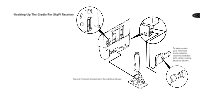
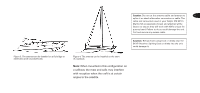
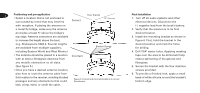
6 Positioning and pre-application Clear Signals • Select a location that is not enclosed or 20° Clearance surrounded by metal that may interfere Correct with reception. If placing the antenna on a metal fly bridge, make sure the antenna protrudes at least 5" above the bridge's top edge. Antenna extensions are available to increase the height above the boat. (e.g. Shakespeare 5228-4. Several lengths are available from multiple suppliers, Blocked Signals including Boaters World and West Marine.) • The antenna should be placed in a location Incorrect with at least a 20-degree clearance from any metallic obstruction on all sides. (See figure 5.) • Once you have a desired antenna location, plan how to route the antenna cable from this location to the receiver, avoiding blocked passages and any obstructions that could Figure 5. Correct and incorrect locations to mount the antenna. kink, crimp, twist, or chafe the cable. Final installation 1. Turn off all audio systems and other electrical devices. Disconnect the (-) negative lead from the boat's battery. 2. Verify that the antenna is in its final desired location. 3. Install the mounting bracket as shown in figure 6. First, hold the bracket in the desired position and mark the holes for drilling. 4. Drill 7/64" starter holes. Applying masking tape over the area to be drilled will help reduce splintering of the gelcoat and fiberglass. 5. Secure the bracket with the four stainless screws provided. 6. To provide a finished look, apply a small bead of white silicone around the bracket's bottom edge.
-
 1
1 -
 2
2 -
 3
3 -
 4
4 -
 5
5 -
 6
6 -
 7
7 -
 8
8 -
 9
9 -
 10
10 -
 11
11 -
 12
12 -
13
-
14
-
15
-
16
 |
 |
