Acer Altos R920 User Manual - Page 183
Introduction
 |
View all Acer Altos R920 manuals
Add to My Manuals
Save this manual to your list of manuals |
Page 183 highlights
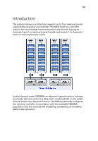
165 Introduction The system's memory architecture supports up to four memory boards organized by branches and channels. The MCH (memory controller hub) on the north bridge has two branches with branch 0 going to channels 0 and 1 or memory board A and B, and branch 1 to channels 2 and 3 or memory board C and D. In dual-channel mode, FBDIMMs on adjacent channels work in lockstep to provide the same cache line data and a combined ECC. In the singlechannel mode only channel 0 is active. The BIOS dynamically configures the memory controller in accordance with the available FBDIMM population and the selected RAS (reliability, availability, serviceability (RAS) mode operation.
-
 1
1 -
2
-
3
-
4
-
5
-
6
-
7
-
8
-
9
-
10
-
11
-
12
-
13
-
14
-
15
-
16
-
17
-
18
-
19
-
20
-
21
-
22
-
23
-
24
-
25
-
26
-
27
-
28
-
29
-
30
-
31
-
32
-
33
-
34
-
35
-
36
-
37
-
38
-
39
-
40
-
41
-
42
-
43
-
44
-
45
-
46
-
47
-
48
-
49
-
50
-
51
-
52
-
53
-
54
-
55
-
56
-
57
-
58
-
59
-
60
-
61
-
62
-
63
-
64
-
65
-
66
-
67
-
68
-
69
-
70
-
71
-
72
-
73
-
74
-
75
-
76
-
77
-
78
-
79
-
80
-
81
-
82
-
83
-
84
-
85
-
86
-
87
-
88
-
89
-
90
-
91
-
92
-
93
-
94
-
95
-
96
-
97
-
98
-
99
-
100
-
101
-
102
-
103
-
104
-
105
-
106
-
107
-
108
-
109
-
110
-
111
-
112
-
113
-
114
-
115
-
116
-
117
-
118
-
119
-
120
-
121
-
122
-
123
-
124
-
125
-
126
-
127
-
128
-
129
-
130
-
131
-
132
-
133
-
134
-
135
-
136
-
137
-
138
-
139
-
140
-
141
-
142
-
143
-
144
-
145
-
146
-
147
-
148
-
149
-
150
-
151
-
152
-
153
-
154
-
155
-
156
-
157
-
158
-
159
-
160
-
161
-
162
-
163
-
164
-
165
-
166
-
167
-
168
-
169
-
170
-
171
-
172
-
173
-
174
-
175
-
176
-
177
-
 178
178 -
 179
179 -
 180
180 -
 181
181 -
 182
182 -
 183
183 -
 184
184 -
 185
185 -
 186
186 -
 187
187 -
 188
188 -
189
-
190
-
191
-
192
-
193
-
194
-
195
-
196
-
197
-
198
-
199
-
200
-
201
-
202
-
203
-
204
-
205
-
206
 |
 |

165
Introduction
The system’s memory architecture supports up to four memory boards
organized by branches and channels. The MCH (memory controller
hub) on the north bridge has two branches with branch 0 going to
channels 0 and 1 or memory board A and B, and branch 1 to channels 2
and 3 or memory board C and D.
In dual-channel mode, FBDIMMs on adjacent channels work in lockstep
to provide the same cache line data and a combined ECC. In the single-
channel mode only channel 0 is active. The BIOS dynamically configures
the memory controller in accordance with the available FBDIMM
population and the selected RAS (reliability, availability, serviceability
(RAS) mode operation.