Acer ARMC_3P User Manual - Page 25
Connecting Power Supply, Package Contents
 |
View all Acer ARMC_3P manuals
Add to My Manuals
Save this manual to your list of manuals |
Page 25 highlights
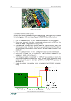
CHAPTER 2: INSTALLATION 13 Connecting with Front Panel Connector There are motherboards which do not have separated pins for power on/off and reset. Both the reset and the power buttons are placed on the system's front panel and connected to the motherboard via a common front panel connector. To allow the connection of the ARMC/3P's remote reset and power on/off signals to those motherboards a special front panel adapter has to be placed between the front panel connector on the motherboard and the cable connector to the front panel. Please ask your local service center for assistance. Connecting Power Supply The ARMC/3P offers the possibility to be powered internally by the host system using the ATX Power Adaptor cable or powered externally using the external Power adaptor. (see Package Contents). Connecting Power using ATX Power Cable Adaptor If the host system provides an ATX 20 or ATX 24 (EPS) connection from the power supply to the motherboard, this cable can be extended with the delivered ATX Power Cable Adaptor. In that case the ARMC/3P is powered internally using the 5V Standby Power of the host power supply. There is no other external power supply necessary. For connecting the ATX Power Cable Adaptor obey the following steps while referring to Figure 7. 1. Power off the host and disconnect it from the power line. 2. Find the ATX cable connecting the host system power supply and the motherboard and remove the cable. 3. Exchange the disconnected cable with the delivered 20-pole ATX Power Cable Adaptor or the 24-pole ATX Power Cable Adaptor (EPS) cable. Then, connect the male connector of the enclosed ATX Power Cable Adaptor to the power supply of the host system and connect the female connector of the enclosed ATX Power Cable Adaptor to the power connector of the motherboard. 4. Connect the ATX Power Cable Adaptor male connector on the ARMC/3P with the 5 pin female connector of the ATX Power Cable Adaptor. Refer to Figure 16 ARMC/3P Host Power pins 5. Check the cabling, finally. Note: Powering the ARMC/3P using ATX Power Cable Adaptor solution requires Standard ATX Power Supply with 5V/2A Standby Power. Refer to the host system and/or power supply manual if the host system and the host power supply fully support the ATX standard.
-
 1
1 -
2
-
3
-
4
-
5
-
6
-
7
-
8
-
9
-
10
-
11
-
12
-
13
-
14
-
15
-
16
-
17
-
18
-
19
-
 20
20 -
 21
21 -
 22
22 -
 23
23 -
 24
24 -
 25
25 -
 26
26 -
 27
27 -
 28
28 -
 29
29 -
 30
30 -
31
-
32
-
33
-
34
-
35
-
36
-
37
-
38
-
39
-
40
-
41
-
42
-
43
-
44
-
45
-
46
-
47
-
48
-
49
-
50
-
51
-
52
-
53
-
54
-
55
-
56
-
57
-
58
-
59
-
60
-
61
-
62
-
63
-
64
-
65
-
66
-
67
-
68
-
69
-
70
-
71
-
72
-
73
-
74
-
75
-
76
-
77
-
78
-
79
-
80
-
81
-
82
-
83
-
84
-
85
-
86
-
87
-
88
-
89
-
90
-
91
-
92
-
93
-
94
-
95
-
96
-
97
-
98
-
99
-
100
-
101
-
102
-
103
-
104
-
105
-
106
-
107
-
108
-
109
-
110
-
111
-
112
-
113
-
114
-
115
-
116
-
117
-
118
-
119
-
120
-
121
-
122
-
123
-
124
-
125
-
126
-
127
-
128
-
129
-
130
-
131
-
132
-
133
-
134
-
135
-
136
 |
 |
